Using SwitchInput for buttons and rotary encoders
SwitchInput is a button and rotary encoder management library that treats button presses and encoder adjustments as events, similar to web and UI applications. Supporting as many switches and rotary encoders as you need, in an event driven way, working along with TaskManagerIO to keep your code clean.
Key points:
- Buttons using either pull down or pull up logic connected directly or via any supported IO expander
- De-bouncing of events on all buttons and encoders to significantly reduce duplicate callbacks.
- Callbacks when a button gets pressed, released or both.
- Indication of a long press (held state) with configurable support for repeat keys.
- Rotary encoder needs no additional components in most cases.
- Works with Arduino, mbed 5/6, ESP on pins, PCF8574, MCP23017 or shift-registers.
You can see SwitchInput in the reference docs
To setup SwitchInput for button management
To initialise switches during setup we call the init method, providing the IO device on which the buttons are connected, the polling mode to use, and setting the default to either pull-up or pull-down. The device could be any of the types defined including I2C expanders, shift registers etc..
// inside setup
void setup() {
    // we default to using IO over arduino pins, see above to change to i2c or shift registers.
    switches.init(ioUsingArduino(), pollingMode, defaultIsPullUp);
}
ioDevicein this case we provided ioUsingArduino() but we could have provided any IoAbstractionRef device, see the IoAbstractionRef documentationpollingModepolling mode is one of SWITCHES_NO_POLLING - all buttons and encoders interrupt driven, SWITCHES_POLL_KEYS_ONLY - interrupt for encoder, keys polled, SWITCHES_POLL_EVERYTHING - everything polled.defaultIsPullUpparameter refers to if the switch is active low (pull-up) or active high (pull-down). Pull-up is the most common because no external components are needed in most cases. When using a switch the input must always be pulled in one direction, because the input pin is very high impedance and will otherwise float between low and high.
Below the diagram shows all three possibilities:

- PU1 - here we use INPUT_PULLUP as the input mode, it enables the internal pull-up resistor, it holds the input HIGH until the switch is pressed, when it pulls the input LOW.
- PU2 - here as above, but we provide an external pull up resistor, needed when either the pin is not pull-up capable or for longer wire runs.
- PD1 - here we use INPUT as the mode, and provide a resistor to GND that holds the input LOW. When the switch is pressed, the input goes HIGH.
To add a button
To add a button there are three possible methods, you can call addSwitch, addSwitchListener or onRelease. Which ever you use, the pin requested will be monitored by switches and appropriate callbacks triggered as events occur. If an interrupt needs to be registered, switches will do it as part of initialisation.
Firstly, lets look at addSwitch, this allows us to add a function to be called back when the user presses the button:
// this function is the callback, name the function as you wish.
void onPressed(uint8_t pin, bool heldDown) {
    // your code for when switch is pressed here.
}

// then in setup to add a button that doesn't repeat
// in this case you get one extra call back when held down
void addSwitch(buttonPin, onPressed);

// or a repeating button simply add the extra parameter
// in this case you are repeatedly called back when held
// invertedLogic allows you to invert the pull-up/down behaviour
void addSwitch(buttonPin, onPressed, repeatInterval, invertedLogic);
You can also register to receive onRelease callbacks, it uses the same listener callback function signature as above. If addSwitch has not previously been called, then the pin is initialised first:
// and if you want to be notified when the button is released..
// the callback is exactly the same signature as for onPressed.
void onRelease(buttonPin, onReleased);
Where:
- buttonPin : the chosen IO port that the button is connected to.
- onPressed : a callback function to receive the notification, specify any function without the brackets.
- repeat: defaults to NO_REPEAT or provide a multiple of twenty milliseconds up to 254 (~5 seconds between events).
- invertLogic : invert the pull-up/down behaviour just for this pin.
You can also add switches using a listener object instead of a callback. The listener must implement the SwitchListener interface which provides methods for handling key presses and releases.
First we create a class that implements the interface and declare a global instance of it, either globally or by using new:
class MyKeyListener : public SwitchListener {
public:
    void onPressed(uint8_t /*pin*/, bool held) override {
        // Called on key press
    }

    void onReleased(uint8_t /*pin*/, bool held) override {
        // Called on key release
    }
} keyListener;
Then during setup we add a switch as follows (other parameters as per addSwitch):
switches.addSwitchListener(buttonPin, &keyListener);
switches.addSwitchListener(buttonPin, &keyListener, repeatInterval);
For both callback and listener forms of addSwitch you can also invert the logic by providing a 4th bool parameter that indicates if the logic should be inverted. To use this form you must always pass the repeat interval:
switches.addSwitch(buttonPin, callbackOrListener, repeatInterval, isInverted);
Using a rotary encoder
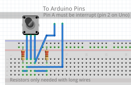
Rotary encoders are fully supported within switches. As of 2.3 they do not need an interrupt in order to work properly, if switches polling mode is "poll everything" the library just polls faster than usual and no interrupts are needed. However, in other polling modes an interrupt capable A pin is needed. Using this library makes working with such encoders simple. Note that rotary encoders use the same IO device that you configured for switches during initialisation - (we fully test encoders on Arduino/mbed pins, PCF8574 and MCP23017).
The switches library will arrange for the interrupt callbacks internally, so all you need to do is follow the instructions below.
First initialise the encoder within setup()
Before creating any encoder objects, we need to create a callback function:
void encoderCallback(int newValue) {
    // do whatever is needed on encoder change
}
For a rotary encoder
void setupRotaryEncoderWithInterrupt(
        uint8_t pinA, uint8_t pinB,
        EncoderCallbackFn callback, // or EncoderListener* instead
        HWAccelerationMode accelerationMode = HWACCEL_REGULAR,
        EncoderType encoderType = FULL_CYCLE);
Where:
- pinA is the A output of the encoder, see notes about polling mode further up.
- pinB is the B output of the encoder
- callback called when there is a change in the encoder value. Either a function is declared as void functionName(int change) or an instance of EncoderListener (see below).
- accelerationMode is the amount of acceleration to apply, defaults to regular.
- encType is optional and defaults to full cycle, covering the vast majority of encoders. QUARTER_CYCLE covers the case for quarter cycle encoders. Thanks to ddd999 for adding this.
Encoder emulation using buttons
To make an encoder with UP, DOWN buttons instead use the following. This will use three buttons:
void setupUpDownButtonEncoder(
         uint8_t buttonUpPin,
         uint8_t buttonDownPin,
         EncoderCallbackFn encoderCallback,
         int speed = 20);
Where:
- buttonUpPin is the pin that the up button is connected to - handled by switches (IoAbstraction)
- buttonDownPin is the pin that the down button is connected to - handled by switches (IoAbstraction)
- callback is called whenever there is a change in the encoder value, declared is void functionName(int change)
- speed is the repeat interval of the button, it defaults to 20 but can be set lower if needed.
To make an encoder with two button control out of a 4 way joystick, that can be shifted between horizontal and vertical scrolling
void setupUpDownButtonEncoder(
            pinid_t pinUp, pinid_t pinDown,
            pinid_t pinLeft, pinid_t pinRight,
            SwitchListener* passThroughListener,
            EncoderCallbackFn cb,
            int speed);
Here in addition to above we also provide the left and right buttons, and a switch listener to use as a pass-through. What happens is when in normal scrolling mode, left and right will be passed through, however, when the intention is set to scrolling sideways mode then up and down will be passed through, with left and right used for scrolling. See the example and reference docs for more details on this. This is used in TcMenu to provide the 4-way joystick support.
Using an EncoderListener OO callback instead
Wherever you can use a callback function to get listener changes, you can also use an OO EncoderListener. First you create a class that extends EncoderListener
class MyEncoderListener : public EncoderListener {
public:
    void encoderHasChanged(int newValue) override {
        // take your action here
    }
} myListener;
Then just replace the encoder callback function with a pointer to the listener, for example:
void setupUpDownButtonEncoder(pinA, pinB, &myListener);
To change the range of values for either of the above
The first call purely initialises the encoder, we then need to change the range of values to be represented by the encoder - maximumValue and also its current value - currentValue. For example, if you set the maximum to 1000 and current to 100, then the range will be 0 to 1000; while the current value would be 100.
Rollover means that encoder runs in an infinite circle (or wrap around), when the maximum is reached go back to the minimum, and when the minimum is reached, go back to the maximum. The step parameter is discussed later in the section along with acceleration.
 	void changeEncoderPrecision(uint16_t maximumValue, uint16_t currentValue,
                                bool rollOver = false, int step = 1);
For all joysticks analog and digital, the scroll direction is often different to the direction for setting values. IE when you are scrolling through menu items and choices, the offset usually increases as you move downward, but this is not the way most people are used to editing values, where they would expect up to increase the value. All encoders support this property, but only joystick based encoders change direction. Further, you can also choose to make the intention direction only (-1 down, 1 up).
setUserIntention(EncoderUserIntention intention);
Where intention is one of: CHANGE_VALUE, SCROLL_THROUGH_ITEMS, DIRECTION_ONLY
Orientation for scrolling / editing
For Up/Down keyboard and Analog Joystick encoders you can also invert the direction by changing the intention. This is important because when using joystick based encoders the natural direction differs between scrolling and setting a value. These two modes have no effect on rotary encoders.
switches.getEncoder()->setUserIntention(intent);
Where intent is one of:
- CHANGE_VALUE - User wishes to change or set a value
- SCROLL_THROUGH_ITEMS - User wishes to scroll through a list of items
- SCROLL_THROUGH_SIDEWAYS - User wishes to scrool through items sideways, such as card layout
- DIRECTION_ONLY - User is just using the encoder for direction only
Rotary Encoders and rate of change
Sometimes the range of values to be edited can be relatively large, large enough to need several turns of the rotary encoder, or for the up / down switches held down for a long time. In these cases we can set up acceleration, by default, any range that requires more than one turn of the encoder will enable acceleration. However, you can control both stepping and acceleration yourself.
Acceleration settings for hardware encoders
To control acceleration on a hardware rotary encoder:
myEncoder.setAccelerationMode(HWAccelerationMode mode);
Where mode is one of:
- HWACCEL_REGULAR - the default, standard acceleration applied
- HWACCEL_SLOWER - acceleration is applied, but less than regular.
- HWACCEL_NONE - no acceleration will be applied.
Changing the step rate of an encoder
At any time the stepping rate of an encoder can be changed, the step must be a multiple of the maximum value for it to work, for example steps of 2 with a maximum value of 100. Without acceleration, this would return: 0, 2, 4, 6, 8, 10 etc.
To change stepping it is the optional last parameter to changePrecision, see further up.
Advanced usage of rotary encoders
You can also use more than one rotary encoder with switches. There is an array internally that stores all the encoders, and each entry is a slot. The "default slot" is 0, and any functions that don't take a slot assume 0. Each entry in the array is basically a pointer to a RotaryEncoder.
You can only initialise encoder 0 (first encoder) using setupRotaryEncoderWithInterrupt or other setup functions described above.
To add additional rotary encoders:
HardwareRotaryEncoder* extraEncoder = new HardwareRotaryEncoder(extraPinA, extraPinB, onExtraValueChange);
switches.setRotaryEncoder(slot, extraEncoder);
Where:
- slot is the slot in the encoder array from 0..3
- encoder is the encoder class itself to be added.
In order to set the precision of an additional encoder:
switches.changeEncoderPrecision(slot, maximum, current);
And again you can set direction only mode by setting maximum and current to 0.
Where:
- slot is the slot in the encoder array from 0..3
- maximum is the largest value that can be represented
- current is the current value to set.
Limitations when using more than one encoder at once
There are a few limitations with multiple encoders. rotary encoders share the same input device as switches. You can either use multi IO described below, or put all switches and encoders on the same device, such as device pins, or an i2c expander (MCP23017 or PCF8574) which is fully supported. If you need more than one expander, or a mix with device pins see MultiIo Secondly, there is a hard limit on the number defined by MAX_ROTARY_ENCODERS that can be changed by altering the file SwitchInput.h should you need more (or less) than 4.
Note that PinA of each encoder must be on an interrupt capable pin, so whichever way you are connecting it each encoder's pinA must be capable of raising interrupts. In all cases switches will register the required interrupts on you behalf.
Common mistakes to avoid
A couple of common mistakes we've seen in the wild that you should avoid:
- Do not initialise
switchesmore than once, this can cause problems - Ensure that you only have one
IoAbtractionRefreferring to any IO device, they cache some important state.
These may be of interest
- Similar - Write XML with GroovyBuilder
- Similar - Wrapping JFreeChart as a Groovy builder
- Similar - Reading XML in groovy using XmlParser
- Similar - Generate an ATOM feed with GroovyBuilder
- Similar - Groovychart Bar chart with fixed colour

Want to let us know about something?
- If this is a library documentation page, raise a PR on the documentation site.
- Open a discussion on the Community channels
- Contact us for problems or improvements on the main site.
Table of contents
- Using SwitchInput for buttons and rotary encoders
- Using a rotary encoder
- Encoder emulation using buttons
- Using an EncoderListener OO callback instead
- To change the range of values for either of the above
- Orientation for scrolling / editing
- Rotary Encoders and rate of change
- Advanced usage of rotary encoders
- Common mistakes to avoid
Supporting us
We maintain several popular embedded projects and work hard to make them even better. If you're looking for commercial services, please do consider us.
Alternatively, you can buy us a coffee to say thanks.
Sharing links
Learn about TcMenu
We build and maintain an embedded menu designer and framework that works on many platforms.