IO Abstraction library fully supports the PCF8574 8-bit and PCF8575 16-bit IO expander chips on Arduino and mbed. It requires only two pins (three for interrupt mode) SDA, SCL, and optionally INT. Our driver integrates the interrupt support for you so you can attach interrupts very easily.
The PCF8574 provides 8 additional input or output ports, but there are few limitations around how the device can be used, and these are discussed below. This device can be used for switches, rotary encoders, and with LiquidCrystalIO.
There's a few things to note about this device:
- Inputs actually set the output to HIGH, and then sense changes on the port. This means that inputs are always INPUT_PULLUP.
- Outputs are quite low current, wire components such that the device is acting as a sink (lower voltage side).
- Interrupts can not be enabled on a per-pin basis, once you register an interrupt, it's for all pins.
- You wire the interrupt pin of the device to a suitable interrupt enabled pin on your Arduino. It is this pin that you provide as
optionalInterruptPin. Omit or set to 0xFF for when you don't want interrupts. - optionalWireClass is the wire implementation class - normally Wire, on Arduino you can omit this.
- This device cannot operate in high speed mode. Therefore, the safe maximum bus speed is 100Khz. Use another device if this is a problem.
Creating an instance
// simplest construction, 8 bit PCF8574 on an address with interrupt
PCF8574IoAbstraction ioExpander(i2cAddress, interruptPin);

// full construction, on Wire1, with 16bit device and inverted logic options.
PCF8574IoAbstraction ioExpander(i2cAddress, interruptPin, &Wire1, is16Bit, inverted);

// simple 16 bit exmaple
PCF8574IoAbstraction ioExpander(i2cAddress, interruptPin, &Wire, true);
We can see above that we simply create an instance of the class, the parameters are full explained in the PCF8574 reference documentation.
Once you have created an instance, simply use it like any other IoAbstraction they all work the same way.
Example usage of the PCF8574
First power down the Arduino and build the circuit below.
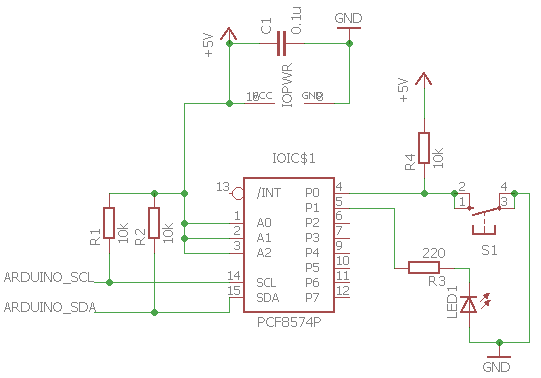
In the circuit below, we connect the PCF8574 IO expansion device to the power (5V-pin16 and GND-pin8) with a 0.1uF decoupling capacitor near the chip between the power rails. Also, note that we must select an address that the chip answers on using A0-A2. Notice that the LED must be connected from 5V to the pin through a resistor, this is the only way it will work, as this chip cannot source very much current, but it can sink a lot more.
To find your i2c device address use this i2c address scanner, this sketch will tell you every address on which it finds an i2c chip.
These may be of interest
- Similar - Write XML with GroovyBuilder
- Similar - Wrapping JFreeChart as a Groovy builder
- Similar - Reading XML in groovy using XmlParser
- Similar - Generate an ATOM feed with GroovyBuilder
- Similar - Groovychart Bar chart with fixed colour

Want to let us know about something?
- If this is a library documentation page, raise a PR on the documentation site.
- Open a discussion on the Community channels
- Contact us for problems or improvements on the main site.
Supporting us
We maintain several popular embedded projects and work hard to make them even better. If you're looking for commercial services, please do consider us.
Alternatively, you can buy us a coffee to say thanks.
Sharing links
Learn about TcMenu
We build and maintain an embedded menu designer and framework that works on many platforms.