Menu library and designer for Arduino and mbed
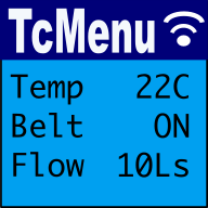
TcMenu is a modular, IoT ready multi-level menu library for Arduino and mbed supporting many input, display and IoT / remote interfaces. It makes presenting configuration, status and operational information much easier.
First, you design your menu structure using the designer UI, then using the code generator you convert your menu structure into Arduino, mbed or Raspberry-PI compatible code that works with your chosen hardware through plugins. The code generator is non-destructive so can be used throughout your project lifecycle.
Further, the designer and code generator are capable of producing localised multi-language menu applications. You can edit the various languages directly within the IDE and then at runtime you can set a compile flag to choose the locale needed.
The below guide will go from design right through to generating a complete, working application:
- Draw out application state and group logically.
- Install the designer UI and embedded libraries.
- Start the designer UI and check everything is set up.
- Create a new project directory to store your embedded application.
- Take the above menu item structures and implement in TcMenu Designer.
- Ensure that EEPROM ranges do not overlap.
- Run the code generator to generate the application.
- Compile the code in your favourite IDE and upload to a board.
- Add more items as needed (round trip between designer and IDE).
Step 1: Draw out your application state and group logically
The first step is to understand your application's state, IE the things that can be configured such as settings, the state that can be changed, such as real time adjustments, and also the status values that provide read only information. We provide an example below for a simple amplifier. If you're moving from another solution this step can probably be skipped.
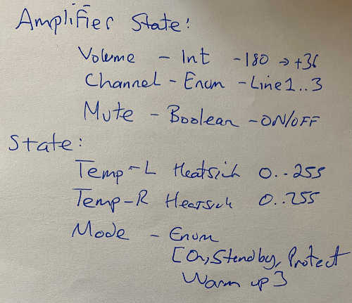
Let's convert this into text:
Amplifier
    Volume - max: 255, offset: -180, divisor: 2, Unit dB
    Channel - enumeratiom of Line1, Line2, Line3
    Status - sub menu
        L Heatsink - Range 0..255, Unit oC, readonly
        R Heatsink - Range 0..255, Unit oC, readonly
        Mode - enumeration of Standby, On, Protect, Warmup - readonly
And at this point we are ready to open the menu designer software.
Step 2 - Get tcMenu Designer - Windows, macOS, Linux
Our Menu Designer software is available to download from the tcMenu releases page. It can design menus and generate code for a wide range of input, display and remote control options. Available as a signed installer for Windows, Notarized app for macOS, and as a Debian package for Linux.
Step 2a: Ensure the Arduino libraries are installed
You will need to install TcMenu library and all dependencies from Arduino IDE, or add the library dependency in the platformIO project ini file. As TcMenu library is built on IOAbstraction library, TaskManagerIO library, SimpleCollections and TcUnicodeHelper it's worth reading a little about these libraries too.
PlatformIO note: Even if you're using platformIO, we recommend that you still download at least tcMenu library initially for the examples. In this case create a libraries directory and put tcMenu in it.
Step 3: Start the designer UI and ensure everything is ready
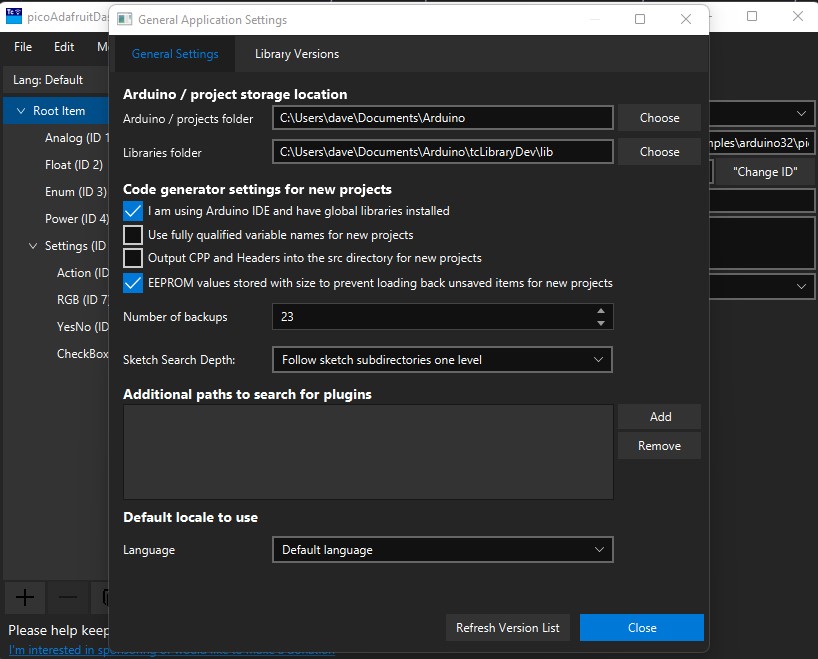
Once you've started the designer choose the "Edit -> General Settings" menu item. From here we can set up the project/sketches folder, and libraries directory. The sketches folder is used to provide a list of sketches, and also the default new project location. The libraries directory is used to check if libraries are up-to-date and also to provide a list of examples. You can always see available and installed versions from the "Library Versions" tab of General Settings.
Here you can also configure how many backups will be kept (they are now in the .backup directory of your project), how deep into both library and project directory structures to scan for examples, and available projects, and also you can setup the global options for new projects. We'll go into these later.
PlatformIO note: users who don't want to have a global copy of the libraries, from Edit -> General Settings untick the "I am using Arduino IDE" option. This turns off all library checking, and will not populate the library examples menu item.
Overview of the application menu options
The application has a main menu, on Windows and Linux it is at the top of the designer window, on macOS it will reside in the system menu area as per other apps.
- "File" Menu contains functions to Open and Save projects, including listing out Examples, Sketches and Recently edited items.
- "Edit" Menu has functions for clipboard, undo/redo and also the Settings dialog.
- "Menu Item" menu contains functions for working with menu items, most are also in the item toolbar bottom-left below the menu tree.
- "Code" menu has the Code Generator, EEPROM validator, internationalization settings, and also a list of IO expanders. It also contains utilities for bitmap/widget creation and font creation.
- "Help" menu has links to the most important parts of the tcMenu documentation. It also has a link to the forum and can prepare diagnostic info too.
Overview of the main window
- From the menu tree, clicking on an item opens it up for editing in the editor area. You can change the values here and they are validated as you type.
- Clicking on the Root item edits the project level properties. From here you can set the unique ID for the project and also the application name that will appear in the title area.
- You can drag and drop items to move them. If you drop near the top of an item the insert point is above, otherwise it will be placed below the item. If you drop into a submenu, it will drop into the submenu instead.
- You can also use copy and paste to move items around the tree, either from the Edit menu, or using regular clipboard shortcuts.
- You can take a copy of a menu tree that can be loaded by the Java or C# API by copying from a point in the tree and pasting into a text editor.
- The prototype view (right) that shows an approximate embedded layout is available from the "Menu Item -> Show Preview" menu. This brings up a lightweight EmbedControl form that is kept in sync as you edit. This is discussed in more detail in the EmbedControl documentation.
Step 4: Create a new project directory to store your embedded application.
At this point you have two choices, either start with an example or a new project. We will start from scratch by choosing File -> New Project.
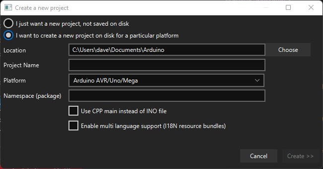
Select the "I want to create a new project on disk" option, this creates a new folder in the chosen location (default is your sketch directory). Type in the name of the project that you want to create, and select an appropriate platform. Advanced: If you want to use a CPP file instead of an INO, tick the "Use CPP" box, and you can enable internationalization support at this point too. Choose appropriate options and click "Create".
PlatformIO note: At this point you will probably want to create a platformio.ini file in this directory for your specific board. Also add the library dependency on tcMenu library at the same time.
Step 5: Take the above menu item structures and implement in TcMenu Designer.
Now we create the menu items based on the state that we identified earlier in Step 1.
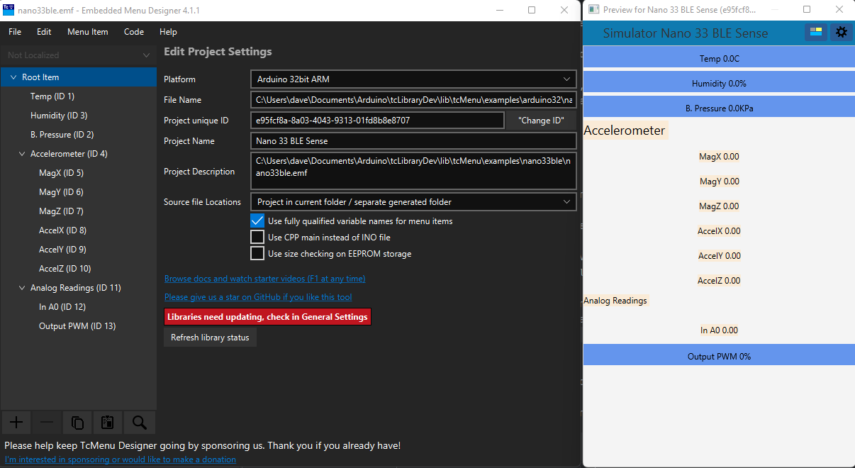
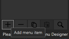
On the left of the main designer window there is a menu tree, this list contains all the menu items within this project and is shown in the main page image below marked (1). To add a menu item we first select the submenu where we'd like it to appear and press the plus button in the menu item toolbar (below the menu tree on the left).
Note that items are created in whichever submenu was selected (or the nearest submenu to the item selected). Below is the create new item dialog:
And once add menu item is pressed:
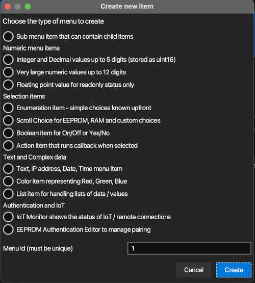
Do not change the ID unless you explicitly want to manage them yourself, it is automatically generated and unique. Simply choose the type of item you want to add and press create. In this case we create a regular numeric editor. The new item will immediately be selected in the tree, and you can start editing its as the name field has the focus.
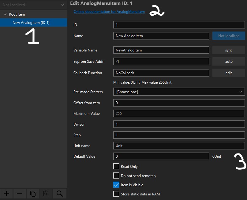
When we select an item in the menu tree (1), its properties become editable on the right-hand side (3). We can change the name, EEPROM storage location (usually by pressing Auto to get the next location), and any properties that are specific to that kind of item. As you edit the values are immediately validated and any errors reported above the item properties.
Each menu item type has a link (2) to comprehensive documentation that explains the intended purpose, how to create the item and full instructions on its usage, including the main functions that you can use to interact with that type of item at runtime.
Callbacks: You can optionally create a callback function that will be notified of any change immediately. However, you can also poll the state of the item as you need to. Both options are fully documented in the menu item documentation; which you can directly access from the link (2) in the designer UI.
Repeat this process until you've fully represented your application state.
At any time you can switch focus to the menu tree by pressing F10, and you can switch focus back to the item properties editor using Esc. You can also search for a menu item in a large structure using F4, all these functions are available from the "Menu Item" menu too until you familiarize yourself with the shortcuts.
Step 6: Ensure EEPROM ranges don't overlap
Before generating a menu, it's a good idea to check that none of the EEPROM ranges or ID values overlap. To do this go to the Code -> Show ID & ROM layout item from the main menu / toolbar. You'll see something similar to the following dialog. Note that there should be no red entries in the EEPROM layout, this signifies that there is an overlap.
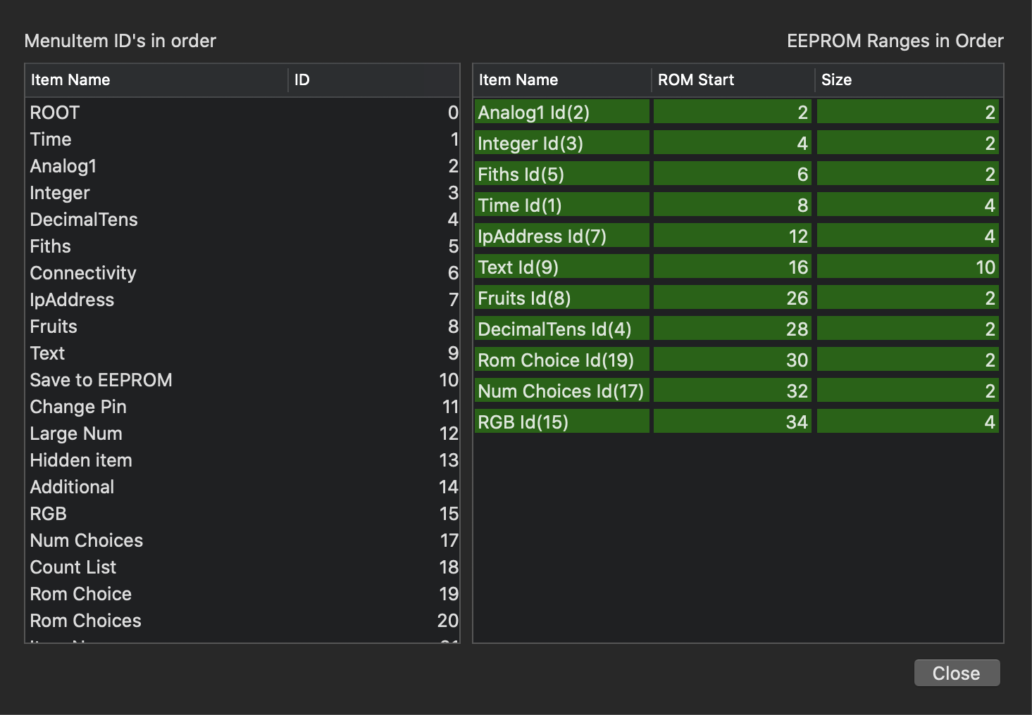
On the right is a representation of the EEPROM memory layout, Each entry shows the start position and number of bytes needed. If the item is in green, it does not overlap with another value. However, any item in red signifies a memory clash. Ensure there are no clashes before generating code.
Step 7: Run the code generator to generate the application
Before proceeding to code generator, on the main designer window select the root item and ensure the application level properties are correct.
Now, we are ready to generate the code, from the main menu select Code -> Generate Code to bring up the following dialog. We'll skip quite a bit of detail here, see the section Generating menu code and plugins for more details.
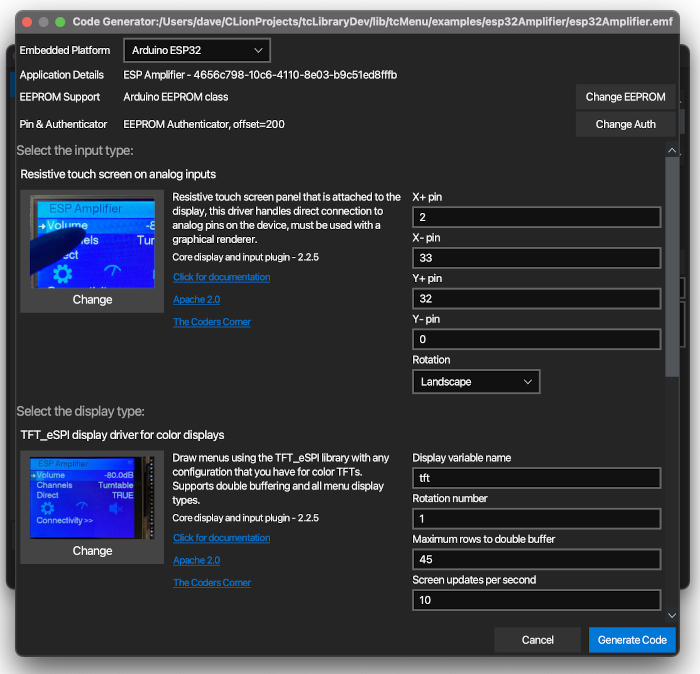
Step 7a: Set up the board type, EEPROM, and Authentication
Before going on to generate any code select the right embedded platform for the board you are targeting. This is important as some plugins are not compatible with all architectures, and the code generation differs slightly for different boards. You also now choose the type of EEPROM that you wish to use, or no EEPROM by clicking the "Choose EEPROM" button. If you have used secured sub menus anywhere, or intend to secure remote connections, an Authenticator will be needed.
Note: An EEPROM will be needed if you use any EEPROM based functions such as load, save, or a ScrollChoice item set to EEPROM mode.
Step 7b: Choose suitable plugins for your hardware
Now that we have defined the basics, it's time to move on to the input, display, and IoT/remote control options. This defines how the user will interact with your application. At this point you need to choose the closest plugins that we have to your hardware.
You'll see the rest of the code generator screen is broken up into three sections:
- Input type
- Display type
- Remote IoT capabilities
For both input and display, click on the image button showing the current plugin that has "Change" underneath it. This presents you with a list of possible plugins, select the most appropriate one and fill in the parameters on the right-hand side. Clicking on the documentation link will take you to the online documentation for that plugin.
If you've used a graphical display, then you will also need to pick a theme. Without going into too much detail that's covered in the linked guide, choose a suitable theme for your display - IE for mono displays choose a mono theme, for color displays choose a color theme.
For now, we recommend leaving the remote / IoT option as no remote.
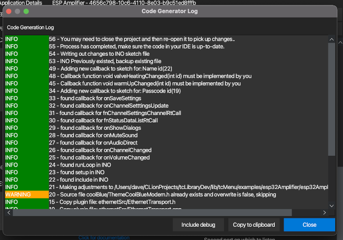
Step 7c: Run the generator
Once you've filled in the parameters for the chosen plugins, the next step is to press Generate and let code generator run. You'll see a log window, it's worth checking through the entries here to ensure everything went as expected.
Step 8: Compile and Upload to your board
You'll now have code in the directory that you generated to. You'll see several files:
- File ending with
.inoormain.cpp- this is the main file with setup and loop methods. - Files ending with
_menu.cppand_menu.h- these contain the menu structures and renderer. - Several other plugin
.cppand.hfiles - these wire up the displays, input and remote technologies.
If you're using things that need wire library, you may need to add Wire.begin to your sketch, and if you're using the inbuilt logging, you may need to start Serial too.
Also see the Designer UI worked example that's a bit out date but still useful for better understanding.
Next steps
The main tcMenu page has a considerable amount of documentation, that covers the vast majority of what you can do with the library.
These may be of interest
- Similar - Write XML with GroovyBuilder
- Similar - Wrapping JFreeChart as a Groovy builder
- Similar - Reading XML in groovy using XmlParser
- Similar - Generate an ATOM feed with GroovyBuilder
- Similar - Groovychart Bar chart with fixed colour

Want to let us know about something?
- If this is a library documentation page, raise a PR on the documentation site.
- Open a discussion on the Community channels
- Contact us for problems or improvements on the main site.
Table of contents
- Menu library and designer for Arduino and mbed
- Step 1: Draw out your application state and group logically
- Step 2 - Get tcMenu Designer - Windows, macOS, Linux
- Step 2a: Ensure the Arduino libraries are installed
- Step 3: Start the designer UI and ensure everything is ready
- Overview of the application menu options
- Overview of the main window
- Step 4: Create a new project directory to store your embedded application.
- Step 5: Take the above menu item structures and implement in TcMenu Designer.
- Step 6: Ensure EEPROM ranges don't overlap
- Step 7: Run the code generator to generate the application
- Step 7a: Set up the board type, EEPROM, and Authentication
- Step 7b: Choose suitable plugins for your hardware
- Step 7c: Run the generator
- Step 8: Compile and Upload to your board
- Next steps
Supporting us
We maintain several popular embedded projects and work hard to make them even better. If you're looking for commercial services, please do consider us.
Alternatively, you can buy us a coffee to say thanks.
Sharing links
Learn about TcMenu
We build and maintain an embedded menu designer and framework that works on many platforms.