In this article I describe how to wire a 20x4 character display to an Arduino. I'm assuming you are using a regular 5V 8bit Arduino, if this is not the case this article will not work for you as you'll need voltage level converters. Most character based LCD displays use the same wiring, but I can't guarantee that all will be the same. If your display is the same it will look like the diagrams on this page and will have 16 pins.
This wiriing diagram assumes you'll be using the excellent LiquidCrystal Arduino library. If you were intending to use a different library to drive the display, then this wiring tutorial may still be useful, but you'd have to check with the library vendors.
Display pin out left to right:
- Vss - connect to ground
- Vdd - connect to 5V supply rail
- Vo - contrast, either connect to potentiometer or smoothed PWM output. See below
- RS - Connect to an Arduino pin, needed by the LiquidCrystal library.
- RW - connect to ground
- E - Connect to an Arduino pin, needed by the LiquidCrystal library.
- D0 - not used
- D1 - not used
- D2 - not used
- D3 - not used
- D4 - connect to Arduino pin, needed by the LiquidCrystal library
- D5 - connect to Arduino pin, needed by the LiquidCrystal library
- D6 - connect to Arduino pin, needed by the LiquidCrystal library
- D7 - connect to Arduino pin, needed by the LiquidCrystal library
- A - Backlight Anode, connect via 220-1K resistor to 5V.
- K - Backlight Cathode, connect to ground.
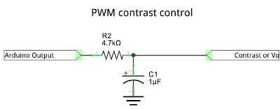
PWM based contrast adjustment
Sometimes, when I use one of these displays, I use a PWM contrast circuit to avoid the need for a potentiometer. The circuit directly below normally works fine from any PWM compatbile output of the Arduino board and does not flicker in a noticeable way. If it does flicker for, just increase the capacitor (C1) size. This circuit connects to display pin 3 of a standard display (the Vo pin). If you don't want to take this approach then just include a potentiometer of at least 10K ohms, the outer connectors go to 5V and ground with the wiper connected to Vo. You'll have to add code to you sketch to set the PWM port to OUTPUT and set the analog level. This code is included below. I found that a value of 90 works well for many displays.
Extra code needed for PWM contrast.
#define DISPLAY_CONTRAST_PIN 3
void setup() {
	pinMode(DISPLAY_CONTRAST_PIN, OUTPUT);
	analogWrite(DISPLAY_CONTRAST_PIN, 90);
	// rest of setup...
}
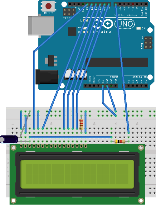
Example breadboard layout
Below is an example of how to layout the breadboard in order to connect the display to the Arduino. This is one example layout, and as you can see it includes the PWM contrast adjustment.
These may be of interest
- Similar - Embed Control developer version for controlling and monitoring Arduino
- Similar - Control embedded menu application from browser - embedCONTROL.js
- Similar - Getting started with tcMenu Turbo
- Similar - Checking if 7segment display is common anode or cathode
- Similar - Arduino multiple digit, 7 segment display tutorial

Want to let us know about something?
- If this is a library documentation page, raise a PR on the documentation site.
- Open a discussion on the Community channels
- Contact us for problems or improvements on the main site.
Supporting us
We maintain several popular embedded projects and work hard to make them even better. If you're looking for commercial services, please do consider us.
Alternatively, you can buy us a coffee to say thanks.
Sharing links
Learn about TcMenu
We build and maintain an embedded menu designer and framework that works on many platforms.