In this tutorial I show you how to connect a 7 segment display to an Arduino board. For a tutorial showing how to drive 4 or 8 digit displays see (Arduino multiple digit, 7 segment display tutorial). Firstly, we must know what type of display we have as there are two possible forms, common cathode and common anode. If the display is common cathode, then the LOWER voltage side is common, if the display is common anode, then the HIGHER voltage side is common. See Checking polarity of 7segment display if you are uncertain of either the polarity or pinout of your display.
Things you’ll need for this tutorial:
- A 7 segment display
- 8 resistors that work with your display (range: 300R-2K2)
- An Arduino board with wire and bread board
Driving a single 7 segment display
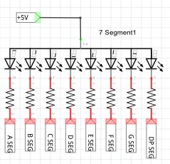
 Far left: the circuit that we are going to build shown as a schematic; where A -G and DP connect to sequential output ports on the Arduino board. Each segment of the display has a resistor in series to lower the current through the LED's. Note that although it may seem quicker to connect one resistor to the common pin, this would alter the brightness of the LED's depending how many segments were turned on.
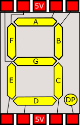
Left: the graphical view of a 7 segment display showing one common arrangement for internal wiring and pin arrangement. This shows a common anode unit so the two center common pins are connected to 5V. For common cathode this would be GND.
At this point, make a note of the starting output, as you will need it later when uploading the program.
For this example, the display was common anode, so therefore COMMON is connected to +5V. Further, we switch OFF the A-G pins to light up a segment. If the display were common cathode, we would reverse this.
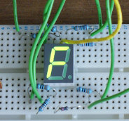
At the bottom of the article is a photo of the circuit running on my prototype board. We also provide a library for driving more than one display (Using Arduino 7 segment LED display library).
Counting in hex on a single 7segment display
Below is the code for Arduino Studio, just paste this code into a new session and Upload once you've built the above circuit, you should get a single display that counts up from 0 - F and resets.
In all 7-segment display examples on this site ledStart is the first output port that you have used (for segment A and all other segments must follow on sequentially). Common should be at either 5V or GND depending on polarity, variable commonHigh should be set to true if common is connected to 5V or false if common is connected to GND.
// set this to the first pin where wiring starts.
int ledStart = 30;

// set to true if the common pin is HIGH, false otherwise
boolean commonHigh = true;


void setup() {
  // Enable all A-G and DP and outputs,
  // set them to OFF (if common is high, then 1 is off).
  for(int i=0;i<8;++i) {
    pinMode(ledStart + i, OUTPUT);
    digitalWrite(ledStart + i, commonHigh?1:0);
  }
}

void loop() {
  // write the number 0 - F (hex)
  // onto the display each half second
  for(int i=0;i<16;i++) {
    writeDigitToDisplay(i);
    delay(500);
  }
}

// Now we define the bits that are on and off
// for each segment, These are used in the
// function below to turn the right bits on.
int dig[16] = {
// bits     6543210
// digits   abcdefg
          0b1111110,//0
          0b0110000,//1
          0b1101101,//2
          0b1111001,//3
          0b0110011,//4
          0b1011011,//5
          0b1011111,//6
          0b1110000,//7
          0b1111111,//8
          0b1111011,//9
          0b1110111,//a
          0b0011111,//b
          0b1001110,//c
          0b0111101,//d
          0b1001111,//e
          0b1000111 //f
};

void writeDigitToDisplay(int digit) {
  // iterate through each bit
  for(int i=0;i<7;++i) {
    // isolate the current bit in the loop.
    int currentBit = (1<<(6-i));
    // and compare with that bit in the digit
    // definition above.
    int bitOn = (currentBit&dig[digit])!=0;

    // if common is high we invert the logic, as 0 is on.
    if(commonHigh) {
      bitOn = !bitOn;
    }

    // and lastly set the bit
    digitalWrite(ledStart+i, bitOn);
  }
}
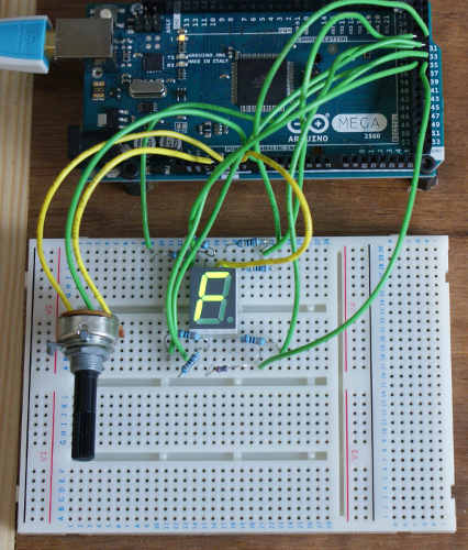
7-segment display built
Continue to Arduino multiple digit 7 segment display tutorial
Another single digit example analog measurements using a single digit 7segment display
Other pages within this category
- Checking if 7segment display is common anode or cathode
- Arduino single 7 segment analog measurement example
- Arduino multiple digit, 7 segment display tutorial
- Wiring a 20x4 character display to an Arduino board
- Arduino 7 segment LED display tutorial
