Measuring voltage from an analog input.
Following on from the previous example ( example for driving 7 segment LED displays ). we now build on the same circuit to make a simple voltage meter.
Additional requirements:
- Potentiometer of at least 10Kohms.
In order to measure voltage, we need to use an Arduino board analog input. Usually these are marked separately as "analog in". We are going to use a potentiometer to adjust the voltage at the analog input.
Background information on potentiometers

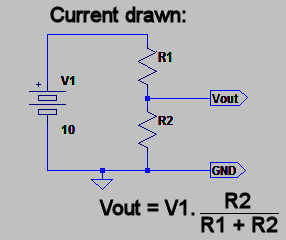
In figure 1 above we see a graphical representation of a potentiometer. We know that a potentiometer has three pins. The outer two are generally connected to the resistive track, while the middle pin is connected to the wiper. As we move the wiper we change the two resistances of the potential divider; which also changes the voltage on the wiper (centre) pin.
This is because we are changing the ratio of the two resistances. Figure 2 shows this as an equivalent circuit. From ohms law we know that current stays the same in series circuits, but the voltage across each component varies.
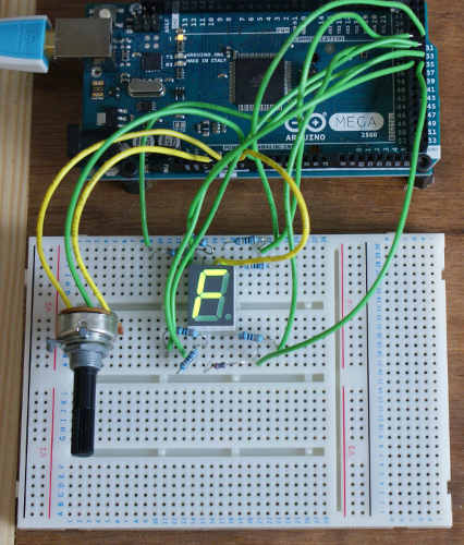
Building the circuit
To try this out, connect one of the potentiometer outer pins to 5V and the other outer pin to ground. Lastly connect the middle pin to an Arduino analog input. You now have a means of varying the voltage on the analog input pin.
Loading the sketch into Arduino IDE.
To run the example copy the code below into a new session and change the variables as follows:
- Variable
ledStartshould be set to the pin you started wiring the LED on, (for segment A and all other segments must follow on sequentially) - Variable
commonHighshould be true if you connected common to 5V, false if you connected it to GND. - Variable
analogInputshould be set to the analog input pin the wiper is connected to.
Once you've made the changes upload them to the board.
// set this to the first pin where wiring starts.
int ledStart = 30;

// the analog input we are going to use
int analogInput = 0;

// set to true if the common pin is HIGH, false otherwise
boolean commonHigh = true;


void setup() {
  // Enable all A-G and DP and outputs,
  // set them to OFF (if common is high, then 1 is off).
  for(int i=0;i<8;++i) {
    pinMode(ledStart + i, OUTPUT);
    digitalWrite(ledStart + i, commonHigh?1:0);
  }
}

void loop() {
  // read and then scale the current voltage.
  int reading = analogRead(analogInput);
  int scaledReading = reading / (1024/16);

  // write the scaled value to the display
  writeDigitToDisplay(scaledReading);

  // small delay to produce less jittery results
  delay(100);
}

// Now we define the bits that are on and off
// for each segment, These are used in the
// function below to turn the right bits on.
int dig[16] = {
// bits     6543210
// digits   abcdefg
          0b1111110,//0
          0b0110000,//1
          0b1101101,//2
          0b1111001,//3
          0b0110011,//4
          0b1011011,//5
          0b1011111,//6
          0b1110000,//7
          0b1111111,//8
          0b1111011,//9
          0b1110111,//a
          0b0011111,//b
          0b1001110,//c
          0b0111101,//d
          0b1001111,//e
          0b1000111 //f
};

void writeDigitToDisplay(int digit) {
  // iterate through each bit
  for(int i=0;i<7;++i) {
    // isolate the current bit in the loop.
    int currentBit = (1<<(6-i));
    // and compare with that bit in the digit
    // definition above.
    int bitOn = (currentBit&dig[digit])!=0;

    // if common is high we invert the logic, as 0 is on.
    if(commonHigh) {
      bitOn = !bitOn;
    }

    // and lastly set the bit
    digitalWrite(ledStart+i, bitOn);
  }
}
Once the below program is running on the Arduino board, move the potentiometer through various positions. As you do so, you should see the value on the display change. We've built a very basic voltage meter (albeit single digit and hexadecimal)!
Move on to the mutliple digit 7-segment display tutorial.
These may be of interest
- Similar - Checking if 7segment display is common anode or cathode
- Similar - Arduino multiple digit, 7 segment display tutorial
- Similar - Arduino 7 segment LED display tutorial
- Similar - Embed Control developer version for controlling and monitoring Arduino
- Similar - Control embedded menu application from browser - embedCONTROL.js

Want to let us know about something?
- If this is a library documentation page, raise a PR on the documentation site.
- Open a discussion on the Community channels
- Contact us for problems or improvements on the main site.
Supporting us
We maintain several popular embedded projects and work hard to make them even better. If you're looking for commercial services, please do consider us.
Alternatively, you can buy us a coffee to say thanks.
Sharing links
Learn about TcMenu
We build and maintain an embedded menu designer and framework that works on many platforms.