There are some occasions when the amount you safely draw (assume 20mA) from an Arduino board pin is just not enough (and some Arduino boards have even lower current capability). In these cases the output needs to be buffered in order to provide more power.
At this point there are several possibilities, including ready made buffer chips such as the ULN2003A. However, in this tutorial we are going to discuss single transistor buffers; which are simple to build, easily understood and good for a few hundred milli-amps.
To start with we are going to look at the NPN transistor, if you are familiar with transistors skip this section.
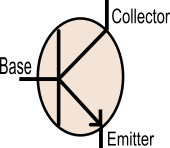
Above, the circuit symbol of an NPN transistor with the three pins labelled. Firstly, the Base controls the flow of current through the Emitter - Collector circuit. Current only starts to flow from the Emitter to Collector when the Base voltage is 0.6V higher than the Emitter.
Load in the Collector (Common emitter)
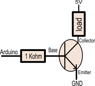
In the diagram above we show a simple buffer, with the load on the collector of the device. When the Arduino output pin is LOW, current will not flow through the load, but when the output pin is HIGH, current will flow through the load. Notice there is a base stopper resistor; which is absolutely essential to avoid damage to both Arduino output and transistor. Without the base resistor, the base would be connected to GND via about 26ohms!
For sizing the base resistor we can either guess at about 500ohm for ~100mA in the collector, or we can calculate from the power needed in the collector/emitter circuit. Knowing the power in the emitter-collector circuit, we know that to keep the transistor fully in saturation we need about 1/10th power on the base. It's better to provide more base current than needed to keep the device in saturation mode, as that keeps the voltage dropped through the transistor to a minimum.
Saturation mode is where the device collector is very close in voltage to the emitter, this therefore reduces heat in the transistor. You can check the datasheet of your transistor to find the exact base saturation current.
A few examples of small signal transistors are: BC109, BC546, 2n2222 but use any small signal NPN transistor you have to hand.
Calculating the base resistor size
First we must work out what base current will flow for a 100mA load:
currentLoad = 100mA
baseCurrentNeeded = 100mA / 10
baseCurrentNeeded = 10mA
And then we must make sure our base resistor is sized sufficiently to ensure it delivers more current than that:
arduinoOutputVoltage = 5V
baseResistor = 500ohm
currentBase = arduinoOutputVoltage / baseResistor
currentBase = 5V / 500
currentBase = 10mA
From the calculation above, we could expect to be able to switch up to 100mA or maybe a bit more with a 470ohm base resistor, and about 200mA with a 220ohm base resistor.
This circuit tends to be very stable, and is the usual go to circuit you'll see recommended for current buffers. You get nearly all of the 5V in the load circuit too.
Switching relays and other inductive loads
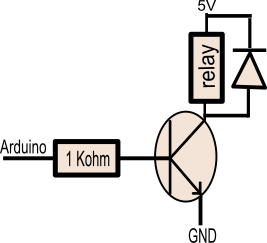
When we wish to switch a relay, an Arduino output will not have sufficient power to activate the relay coil, therefore we normally use the common emitter circuit, but with an additional freewheel diode that prevents (potentially quite high) voltage spikes damaging the transistor during switching off.
When we turn off a relay, the coil being an inductor stores a charge. As an inductor is a low pass filter, it uses this charge to react against the sudden switching off of the circuit. Looking at the additional diode, we can see that it would only conduct if the voltage at the collector exceeded 5V plus the diode forward voltage, thus protecting the transistor from voltage spikes.
If you find during start-up / reset that the relay is switching, then you can connect a 10K resistor between the pin and GND, before the base resistor. This keeps the transistor turned OFF even if the Arduino pin is floating.
Load in the emitter (Emitter follower, Common collector)
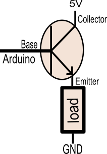
Another option is to put the load into the emitter as shown above. When the output is taken from the emitter of the transistor, nearly the same voltage as is on the base appears on the emitter, it's actually very similar to putting a forward bias diode in the circuit. This means that if we had 5V on the base, we'd expect to see 4.4V on the emitter going into the load.
When putting the load in the emitter, we don't need a base resistor, because the base current is a factor of the current seen by the emitter. Never rely on anything other than the minimum hfe value provided.
For examples sake lets assume a minimum gain of 50 specified on our datasheet:
emitterCurrent = 300mA
gain(hfe) = 50
baseCurrent = emitterCurrent / gain(hfe)
baseCurrent = 300mA / 50
baseCurrent = 6mA ( don't rely on it being any better than this ).
In the above example we see that for a 300mA load, the Arduino would see a much lower current of about 6mA. However, that 300mA load would result in at least 30mA of dissipation in the transistor causing heat. As before, don't rely on this for more than 200-300mA.
This circuit has a few drawbacks, the biggest being that we cannot switch the full 5V, best case is about 4.4V; which may not be enough for all purposes. It's advantage however, is that it does not need as much current from the Arduino as the above example.
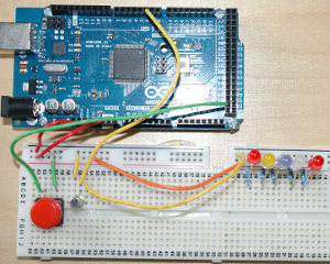
Emitter follower output buffer example
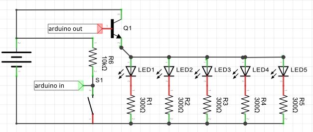
Above is an example circuit with the load in the emitter driving many LED's (where the lower voltage doesn't matter). In the sketch we use a PWM pin to turn the lights on and off slowly when the button is pressed. The calculations for this circuit:
Voltage Across Resistor
 5.0V (Arduino Voltage)
-0.6V (loss in transistor buffer)
-1.2V (loss in red led)
=3.2V

current per LED by ohms law
 3.2V / 330ohm     = 9.6mA    (or about 50mA for 5)
Here is the Arduino studio code for the example:
/*
 * Arduino example code for the transistor buffer example.
 *
 * Switches an LED on slowly when the button is pressed by using a
 * PWM output to fade in or out the LED's.

 * by thecoderscorner.com
 */

char buttonInput = 52;
char pwmOutput = 2;

int currentDirection = -1;
int brightness = 0;
void setup() {
   pinMode(buttonInput, INPUT);
   pinMode(pwmOutput, OUTPUT);
}

void loop() {
  // check if the button is pressed, and based on that decide if we are to
  // fade in or out the LEDs
  if(digitalRead(buttonInput) == LOW) {
    currentDirection = +1;
  }
  else{
    currentDirection = -1;
    digitalWrite(pwmOutput, LOW);
  }

  // now adjust the brightness if we are not at minimum or maximum.
  if(brightness > 0 && currentDirection == -1) {
    brightness = brightness - 1;
  }
  else if(brightness < 254 && currentDirection == 1) {
    brightness = brightness + 1;
  }

  // change the LED to represent the new brightness.
  analogWrite(pwmOutput, brightness);

  delay(10);
}
More detailed explanation of emitter follower
The base to emitter junction acts like a forward biased diode, in that it has a forward bias voltage, because of this we get a 0.6V difference from the base to the emitter. The base to collector junction normally is reverse biased, we get conduction when the base is charged (and current gain) because the base is extremely thin in comparison with the emitter so most of the current flows up to the collector missing the base. This explanation is greatly simplified but adequate for our purpose, I recommend the following free online text if you wish to understand transistors better
Also, in any production circuit, always have a suitably sized bypass capacitor between 5V and GND near to your buffer. You'll be switching a lot of current and don't want noise on the power!
These may be of interest
- Similar - Detecting power loss in a power supply
- Similar - Arduino to PC communication using USB serial and Java
- Similar - SPI Serial Peripheral interface for Arduino tutorial
- Similar - Designing a simple PGA2310 based preamplifier with network control
- Similar - Unit testing embedded and Arduino projects

Want to let us know about something?
- If this is a library documentation page, raise a PR on the documentation site.
- Open a discussion on the Community channels
- Contact us for problems or improvements on the main site.
Table of contents
Supporting us
We maintain several popular embedded projects and work hard to make them even better. If you're looking for commercial services, please do consider us.
Alternatively, you can buy us a coffee to say thanks.
Sharing links
Learn about TcMenu
We build and maintain an embedded menu designer and framework that works on many platforms.