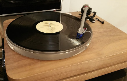
 Orbit is a high performance DIY turntable based on Rega 24V decks. It's very easy to make using a
moderately well stocked home workshop. In my opinion it competes well with decks costing a lot more
than its sum of parts. It uses a fairly conventional design so that it is easy to fit the original
Rega lid back onto it, this is important as a lid protects the fragile stylus when not in use and
prevents dust reaching the deck.
Orbit is a high performance DIY turntable based on Rega 24V decks. It's very easy to make using a
moderately well stocked home workshop. In my opinion it competes well with decks costing a lot more
than its sum of parts. It uses a fairly conventional design so that it is easy to fit the original
Rega lid back onto it, this is important as a lid protects the fragile stylus when not in use and
prevents dust reaching the deck.
What I really like about Rega decks is that they are very easy to upgrade. In fact there is no need to perform all upgrades in one go, one can start with the TT PSU, then the platter and sub-platter and so on. This means a high performing deck can be purchased slowly in steps. In fact my first attempt at building a turntable involved a series of ISOKinetik modifications on a P3/24 turntable.
I’ve come a long way since then, and this page shows where Orbit is now. I’m not saying it’s at superstar status or anything similar, but it’s certainly enough that it’s made this audiophile very happy. This turntable is the result of a lot of reading through forums and books, many thanks to each of the sources I’ve read over the past couple of years, there are so many sources of information that it would be difficult to list them all here.
Parts used to make Orbit:
- Orbit Rega arm ( see separate article )
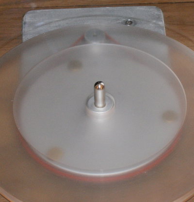
- ISOKinetik platter and sub-platter
- ISOKinetik bearing and housing
- motor circuits and PSU.
- 15mm baltic birch plywood (platter and sub platter)
- 4mm aluminium (motor chassis)
Due diligence and safety
Before proceeding further, if you follow this guide, you accept that you’ll be taking a perfectly good working deck, and completely stripping it down. Further, much of this article discusses using potentially dangerous power tools. If you are in any doubt that you can perform these tasks, it’s best not to attempt it. Michell engineering, Inspire HI-FI and IsoKinetik all offer fairly similar ready made arrangements at reasonable cost.
Building a plinth from highest grade Baltic birch plywood.
In my opinion a turntable needs a solid plinth, the more material the better. This helps to reduce the amount of acoustic energy that gets into the block in the first place.
High grade Baltic birch plywood is my material of choice for enclosures and panels where I want to control resonance. This can normally be sourced from specialist hardwood stores. For this design I used glued together 15mm birch plywood sheets veneered with walnut. The motor is mounted on an isolated 4mm aluminium chassis. Brushed aluminium is not needed simply sand the finished part with 300, 600 then 1000 grit sandpaper and you’ll achieve an adequate result.
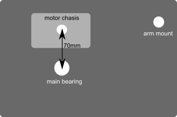
Firstly, this design uses the same overall dimensions as the Rega plinth you already have. So you can mark out the holes for the arm and main bearing based on the original plinth. For the motor, there is little tolerance as the belt must fit. As the motor is on a separate aluminium chassis, my suggestion is that you only cut the motor and bolt mountings once you’ve done a test fit.
From the image above, it can be seen that the corners are rounded. This produces a design that is aesthetically pleasing and may help to reduce vibrations as there are no corners. If, as with me this turntable is going in the living room, the former requirement is more important. If we allow ourselves enough time, and do not rush, the deck should look entirely professional.
Plinth plans

above main bearing and arm shown in cross section view, note the bottom area of the main bearing is inset, this is required because otherwise the bearing will not be long enough.
above the motor cutout area is shown, where the 4mm alu chassis is fitted, recessed at least 2mm into the wood. There needs to be room for the motor to fit in the cut out.

Above the motor cutout shown in cross section view, where the aluminium chassis is recessed into the plinth.
Cutting the template
For this design the plinth will be 45mm thick plus veneer and the sub plinth will be 30 mm thick. This will be achieved using laminations of 15mm ply. Therefore, we are going to make 5 pieces of plywood to the same outer dimensions, so the first thing we need is a router template. For this type of work, the easiest way to proceed is to use a copy bit. This is a router cutting bit with a bearing at the bottom that traces a shape. To mark out the corners I used a large roll of insulation tape to draw the rounded corners. Following this, I cut the template with a jigsaw and smoothed out any irregularities with a belt sander. Now on the template mark out the motor cutout where the aluminium chassis goes and also the arm mount and bearing.
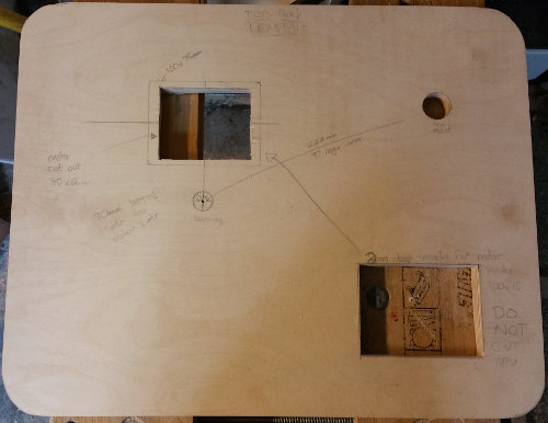
Above, the template I used to cut out the 3 plinth and 2 sub plinth panels. It also had the motor cut out templates included within it.
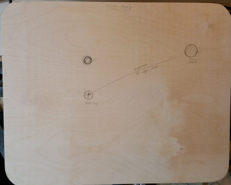
Above, the top panel, with the arm and bearing points marked, these are only drilled once the plinth is glued together.
Note routers can only take off a few millimetres of material at once, so roughly cut the 5 plinth and sub plinth piece corners a bit larger than needed, then use the copy bit and the template to finish the corners. Remember that routers go left. Once this is done, all 5 pieces should perfectly align.
Cutting out the motor area
Before gluing together, the motor cutout needs to be made in each of the top 3 pieces, there’s no magic rule for the size, just ensure you can easily mount the motor, my final metal chassis size was 100x75 allowing about 6-7mm overlap. Again, make sure the motor fits. Don’t leave this until last or you’ll have to cut through 45mm of material at once!
At this point on the top piece you’ll need to use the router to make the 3mm inset for the motor chassis to go into. Then cut the aluminium sheet to fit into the inset. Once everything is test fitted, only at this point should you drill the centre hole for the motor pulley and the two bolts.
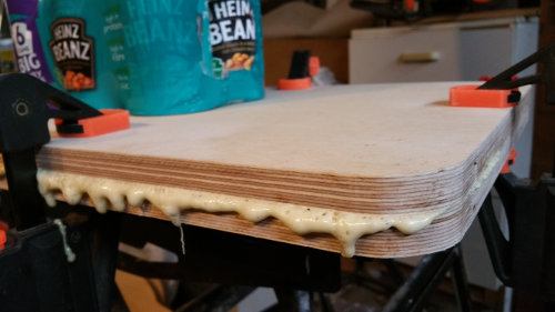
Putting the parts together
At this point we need to assemble the plinth and sub plinth. I recommend using a polyurethane wood glue and lots of clamps and weight for a few hours. What was recommended to me at the shop is to roughen up the pieces to be joined.
Once the glue is set, work out where the motor control PCB is going to be put, and cut out the sub plinth where the PCB will be. Now is the time to mount the motor in the metal chassis. Use silicone to stick the chassis to the wood, and use VHB tape to stick the motor to the metal chassis, along with two M3 bolts. I used standard PCB spacers to mount the motor PCB to the plinth and just used a bit of glue gun glue to hold it in place.
In between the plinth and sub-plinth I recommend sorbothene, Malvern audio do 50x50x10 blocks and these work very well. On the sub plinth I use rega P9 feet. Fitting the arm should be fairly self-explanatory, as should mounting the main bearing. Note that the main bearing should not be too tight. Only tighten by hand. I’ve not made any mentions of my arm here, which has also been modified significantly, this is being documented as well.
Adjusting the lid to fit
In order to use the Rega lid with the rounded corners, you'll need to reset the lid mounting points. I just drilled new holes and used rivets to hold everything in place, see below. Use the largest rivets that will fit, and use the face side against the softer plastic of the hinge.
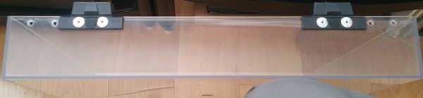
The hinges remounted at a new location, that is compatible with the rounded corners.
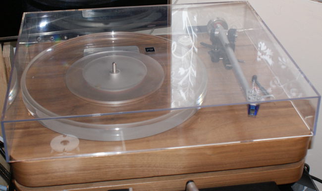
turntable fully assembled with lid.
Other pages within this category
- HI-FI Collective cable kit 6
- Orbit, a high performance DIY turntable.
- Things learnt from building the first turntable.
- Turntable building - the history
You'll also find me on:


Also find me here