<img class=" titleimg" alt="original TT" src="/images/audio/turntable/tt-complete1.jpg"/>
Before my most recent turntable build, I had tried a couple of earlier designs. The first of which was a Rega deck with a couple of IsoKinetik modifications. I've gone a long long way since this, but I keep it here for historic purposes.
Starting out with a P3-24 deck.
My deck started life as a refurbished P3-24 unit, with no mods made to it. Firstly, after much reading I purchased the TT motor control unit; which is available from many retailers at reasonable cost. It should be said that this is one of the easiest and most effective upgrades that you can me, and I would not do any other jobs without first using the TT motor control unit.
At this point I realised that I'd have to move up from the built in phono stage in the Roksan K2 amplifier, so I went with Project Tubebox IIse, which as with many other parts I got from Analogue Seduction.
Following this I went on to change the platter, sub platter and belt. I went with ISO Kinetik for both the sub platter and platter. These again made significant improvements when paired up with the white Rega belt. At this time I also changed the feet to P9 feet (on reflection now if starting from scratch I'd use sorbothene).
Reasoning behind this design
In my opinion, a turntable plinth needs to be very strong, with as little resonance as possible, this because the arm and platter would otherwise be subject to these resonances and distortion would result.
So with this in mind and having recently finished reading a good book on acoustics (the master handbook of acoustics) I thought to myself that a rectangular plinth was probably not a good starting point. In fact lets step back for a minute and ask "what does the plinth need to do": hold the motor, arm and platter in position while producing as little vibration as possible.
I had about half a sheet of very high quality 18mm Superior grade birch plywood left over from building my speakers, and this stuff is dense with about 15 ply per 20mm and is 100% void free. It's expensive, but many high end products that cost thousands often use this very type of ply, because it is the best.
This design is somewhat like a polo mint, but with a solid layer at the top, to be honest it did not work as well as I initially expected, and I had to brace the top layer, where the motor mounts to get things just about acceptable.
It was designed from several layers of plywood glued together. The top layer was not cut like a polo, and instead had an arm mounting point for Rega and the cutouts for the motor and the main bearing.
Now for the plinth deep dive - if interested
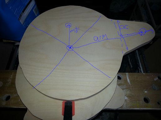
For the top piece of the plinth that needs to accommodate the motor, the platter support bearing and the arm I cut this out per the image below. Of note, the centre of the motor spindle (mtr) is 70mm from the platter bearing, and the centre of the (arm) has to be 222mm from the center of the platter bearing. The motor to spindle must be quite accurate to ensure the belt fits properly.
Below there is an illustrated image showing the cut-out for the plinth top piece and the arm extension (ac) is probably open to a bit of artistic adjustment, but it must allow the arm to be fitted 222mm from the platter centre point. My measurements for (ac) are extending out by about 110mm in each dimension, one just over one just under. However you can decide, but make sure that it will be possible to mount the arm.
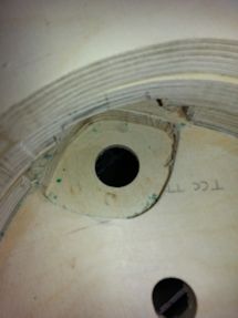
Of note the motor must be routed out underneath leaving not more than a 1/4" inch of material. This is because the motor pulley is not long enough to reach right through. You'll also need the router to carve out some of the base plinth at the appropriate point where the motor is to at least 25mm deep so that the motor fits. This has the advantage that much of the motor area is braced by the base plinth, making up for the lack of material around the motor area.
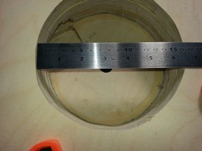
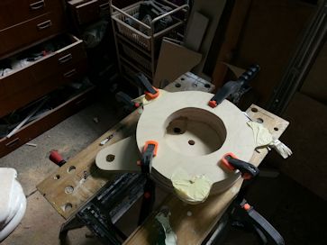
Also drill out the hole for the rega platter bearing in the middle, and the arm ensuring they are only just big enough. See images below. This is the point at which I stripped down the donor deck to get the motor and bearing sizes. Once all the drilling is done do a test fit before gluing the two parts together, ensuring that you can fit the motor. Then glue the parts and clamp until set.
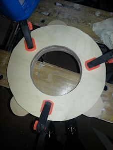
Left: plinth being glued together. Right: motor cutout.
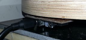
Left: plinth being glued. Right: motor control circuit mounted onto bottom of unit.
Finishing up
This is the hard bit, as the turntable is going to be pride of place, on the top of the HIFI shelf for all to see it has to look good. This part took me best part of a day on its own, to sand the visible parts as best I could, and apply two coats of clear varnish. Any imperfections will be very visible once varnished so all I can say is this is not the area to skimp. It will be looked at by a lot of people for time to come!
Fitting the feet is a bit trial and error, but here are a few pointers, never fit a foot directly in line with the arm mount point, find three dead points in the base (I did it by suspending the deck and tapping lightly around the base while lightly holding the arm mount point. It's easier to do than you'd think but again takes time. I used rega P9 feet that are easily available online.
Putting the components on the plinth
Once all this is done, you can now fit all the components, pretty much in the same way that they came off the p3 deck. First install the centre platter bearing and tighten the nut underneath. Next the motor should be glued into the routed out area and check that the belt fits OK, I used a fast drying evo-stick for this, but any general purpose adhesive would do. The motor control circuit I glued to the opposite underside of the deck from the arm using a hot glue applicator and some small plastic feet. Lastly, I mounted the arm with three countersunk, hex M3 35mm bolts using locking nuts and two washers on each. Use the countersunk variety as they work best with the arm, I found that Falcon workshop supplies have a really good range of longer M3 bolts and locking nuts.
In order to make the design quiet, I had to earth the motor to the phono-stage ground. Doing this entirely removed unwanted motor noise artefacts. One last adjustment I had to make, was to brace the underside of the top plinth as can be seen in the diagram below.

Other pages within this category
- HI-FI Collective cable kit 6
- Orbit, a high performance DIY turntable.
- Things learnt from building the first turntable.
- Turntable building - the history
You'll also find me on:


Also find me here