In this article, I present an example showing how to connect an Arduino device to your PC using USB serial and Java. USB serial is available on nearly all Arduino based boards. Further, there are serial interface Java libraries that can connect to an Arduino.
If you are unfamiliar with data communications in general, take a look a the introduction to data communications article; although it does not cover serial communication, it is still a good starting point for the unfamiliar.
We recommend tc-menu library not only provides a full menu system with designer, but also remote control from Arduino to Java using RS232 or Ethernet.
This will require that you have the following components to hand:
- Arduino device with breadboard and jumper wire
- 20x4 LCD display
- some microswitches & 4k7 resistors
- USB Connection to a computer (serial over USB)
- Java version 8 on the PC / Mac
- The data-comms project sourcecode
- A suitable Java IDE, I recommend IntelliJ IDEA
Once you have all of the above, firstly you’ll want to wire a 20x4 display to the Arduino as per the link. Take note of the ports used for the various connectors as they will be needed to set up the sketch later. Note that this script uses PWM contrast based on the link above.
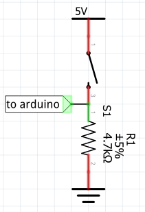 Now wire the switches in as well, each switch should be wired to the board as per the example circuit on the left
(never use less that a 4k7 resistor for this or the current drain will increase). At 4k7 the current drain for
each switch when on is about 1mA; which is not particurly high even with a few switches normally on.
Now wire the switches in as well, each switch should be wired to the board as per the example circuit on the left
(never use less that a 4k7 resistor for this or the current drain will increase). At 4k7 the current drain for
each switch when on is about 1mA; which is not particurly high even with a few switches normally on.
At this point you should have both the 20x4 display and a few switches connected according the circuit above.
Now is the time to load the code onto the Arduino device. Switching to the PC, within the source code you’ll see a
directory called arduino/commandServerRS232, this is the Arduino code, copy it into your Arduino folder, normally under
the home area or Documents on Windows. In the script there are some changes that need to be made, in order to tell the
script where to expect the LCD display and also the buttons.
Setting up the arduino sketch to run
Once everything is wired up, you will need to enter the pins used for the display and switches noted earlier into the sketch. Change the constants at the top of the sketch as shown in the example below (using your own settings). In my example I had the buttons connected on bins 24-26.
#define BUTTON1_PIN  24
#define BUTTON2_PIN  25
#define BUTTON3_PIN  26
Now we configure the serial communication speed, I set it to be 9600 baud but over USB, it can reliably run faster.
// this is the speed at which to initiate the serial over USB connection
#define PORT_SPEED 9600
Lastly, indicate which ports you wired up your LCD display to.
// this is the standard configuration of the LCD display. Change the pin assignments
#define RS_PIN 28
#define ENABLE_PIN 29
#define DISPLAY_CONTRAST_PIN 3
#define D0_PIN 30
#define D1_PIN 31
#define D2_PIN 32
#define D3_PIN 33
LiquidCrystal lcd(RS_PIN, ENABLE_PIN, D0_PIN, D1_PIN, D2_PIN, D3_PIN);
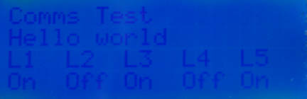
As long as all is wired up correctly you should be able to run the script on your Arduino, the display should initialise
and look like the example below. If not, switch off and check your wiring and code carefully. The PWM contrast setting
can be adjusted in the setup() section of the script.
Building the Java code on your PC / Mac
Now is the time to obtain and build the Java source on your PC / Mac.
For Java development I recommend IntelliJ IDEA that I use myself and has both free
and commercial versions available for PC / Mac / Linux. Most Java IDE’s will be able to import the maven pom.xml as
a new project, if you use this method all dependencies will be obtained automatically using the maven POM.
There are several examples contained within the code, you want to look in the com.thecoderscorner.example.datacomms.rs232commands
package. In order to run the project, run the class:
com.thecoderscorner.example.datacomms.rs232commands.ui.ArduinoControlApp
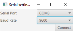
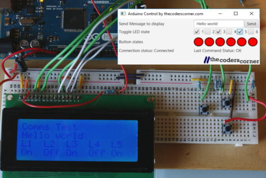
If all is working at this point you should see the serial settings dialog requesting the port and speed (above left), choose the usual serial (COM) port that Arduino studio is using, and set the speed to 9600 or whatever you set the Arduino side to.
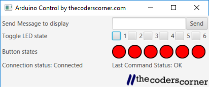
Once done you should see the main screen (above right), Connection status is shown in the lower left corner, and the status of the last command sent on the lower right.
Sending a text message to the 20x4 display
To send a text message to the server, type some text in the text box and press send, the text will be transmitted to the server and displayed on the 20x4 display. You’ll see the last command status will be set to OK very soon afterwards and the text will be on the 20x4 display on the board.
Pressing any switches on the board
Likewise if you press any of the switches connected to the Arduino, they will show on the Java UI at the next status interval (set to approx 1 second on the sketch). There is a combined status update sent by the board every second that includes the latest switch states.
Changing the LED combo boxes on the PC
If you tick any of the combo boxes in the Java application, you’ll see the L1 - 5 change on the Arduino display.
More about the Java application
The Java application is split into two parts, User interface and data communication components, the communication
components are in the protocol package, while the user interface parts are in the ui package. SimpleRS232ArduinoController
is where the serial communication to / from the Arduino take place. It implements the interface ArduinoInterfaceControl
of which there is another implementation that works standalone, for running the application without a board
connected to your PC / Mac.
There are two Windows in the application, both are Java FX based and use the FXML format. They can be loaded into Scene Builder and designed graphically. There is a resources directory that contains both of the FXML design files and a logo.
Other pages within this category
- SPI Serial Peripheral interface for Arduino tutorial
- Arduino to PC communication using USB serial and Java
- Message based communication using sockets.
- Using sockets for a character based stream
- Data communications by example for developers
You'll also find me on:

Also find me here