In this tutorial, I present a fictional SPI chip that we will use for the sake of example. This chip has two LED’s and controls them over SPI. It will help us to understand SPI with a real worked example. Following on we will build a real world circuit, using the SPI library, to see how easy it is to use SPI on Arduino.
Serial Peripheral Interface (SPI) Introduction
Serial communication allows less pins to be used to communicate information between two chips or boards, and also removes a whole class of timing issues that are associated with parallel communication. However, in order for serial communication to work, there needs to be a clock. Without the clock we would not know when a new bit was available on the data pin. New data arrives on each clock cycle, and the chip generally “shifts” that data into it’s internal registers.
SPI requires three pins plus a chip select, these are as follows:
| Line | Our Name | Meaning |
|---|---|---|
| SCLK | Clock | The serial clock for each data transition |
| MOSI | Data Out | The data line going FROM master TO device |
| MISO | Data In | The data line going TO master FROM device |
| CS | Chip Sel | The chip must be selected in order to process instructions |
As we can see above, whenever SPI communication occurs, it is always in two directions, we may not need one side of the communications, but by virtue of the two line system, it is possible to send and receive at the same time. To make things easier, if the chip you are addressing is uni-directional, then you only need wire up the direction you want. You always need clock and chip selection however.
If we look at the diagram below, we can see three of the pin-outs from the above table presented graphically, with the data line changing with each clock transition. Further, the chip must be selected in order for communication to work. Having the chip select line allows us to put more than on chip on the same serial bus. With SPI there is no need to “pull up” the lines with resistors like those needed with I2C.
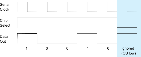
Example SPI sequence sent to chip
Example SuperChip SPI communication
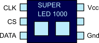
For the rest of the example lets create a fictional chip called SuperCHIP. It has two LED’s that can be programmed using SPI.
Chip we will use for SPI demonstration purposes.
Above is the chip we will use for the rest of this example. It has two LEDs that we can turn on/off
using an SPI command. The command is made up of 5 bits, where two of the bits represent the LEDs and
three of the bits represent the register we are adjusting. This chip is uni-directional, and therefore
only the Clock, Master Out Slave In and chip-select need be wired to the master.
Most SPI chips have either registers or commands, these allow us to perform operations on the chip. For
example the 8 bit IO drivers such as PCF8574 have a register that represents its IO pins. In our example
we have a two bit register that is write only, it is written to on address b100 (4). We assume that the
byte ordering is most significant first (big endian).
| Bit | Meaning |
|---|---|
| 0 | Bit 1 of the command |
| 1 | Bit 2 of the command |
| 2 | Bit 3 of the command |
| 3 | LED 1 state |
| 4 | LED 2 state |
At the moment our chip has one command
| Sequence | Data | Description |
|---|---|---|
| b100 | 2 bits | Change status of LEDs to the 2 bits provided in the data. |
So if we wanted to send the change command, we’d do it as follows in pseudo code:
set the chip select
array_of_bits = [1, 0, 0, 1, 0]
for each BIT in array_of_bits
    set the clock low
    set data out pin to BIT
    set the clock high
end
set the clock low
unset the chip select.
In fact, if we look at the example SPI data sequence diagram earlier, we can see that this is the same as the pseudo code presented above. Fortunately, to use SPI on an Arduino, we don’t have to concern ourselves with the above, it’s done for us in hardware and managed by a library.
SPI Modes, endian’s and such
When we communicate over any protocol, we must be clear how the devices will transition from one bit of data to the next, generally there are two main possibilities; leading edge trigger and falling edge trigger. With leading edge triggering, the transition takes place as the clock line goes climbs from 0V up to 5V. Whereas with falling edge the opposite is true.
Endian’s define which data goes first, Least significant bit or most significant bit. Let’s say we want to transmit the number 23, that is bits 5, 3, 2 and 1 ON. If you’ve got the endian wrong, the communications just won’t work. For more detail see the Arduino site SPI example.
| Bit number | 1 | 2 | 3 | 4 | 5 | 6 | 7 | 8 |
|---|---|---|---|---|---|---|---|---|
| Big Endian | 0 | 0 | 0 | 1 | 0 | 1 | 1 | 1 |
| Little Endian | 1 | 1 | 1 | 0 | 1 | 0 | 0 | 0 |
In arduino we set these values using SPISettings and pass that to the beginTransaction method. An example is included below:
SPISettings potSettings(<bus-speed>, MSBFIRST, SPI_MODE0);
SPI.beginTransaction(potSettings)
Using SPI on Arduino
Arduino uses AVR based processors; they have built in SPI support that provides very fast hardware SPI via an easy to use library. Here we use it to program a digital potentiometer that controls an LED. This circuit has three switches to control the brightness.
Components needed:
- 3 micro-switches
- 3 4k7 (or larger) resistors
- 1 220R resistor (or near value)
- 1 SPI digital potentiometer (I used MCP4131)
- 1 red LED
- Arduino break-out board
- Jump wire kit.
Building the circuit and uploading the code
When we press the UP button the LED brightness increases, DOWN reduces the brightness, RESET clears the current state. The circuit diagram is below, and the parts are readily available. The only additional component you may need is a moderately sized capacitor (1 - 10uF) on the power rail to ground near the device. This rail capacitor is quite common with most IC’s, op-amps tend to need a rail capacitor too for stability.
Each switch has a 4k7 resistor as a pull down, if you don’t have 4k7 use a size larger - not smaller.
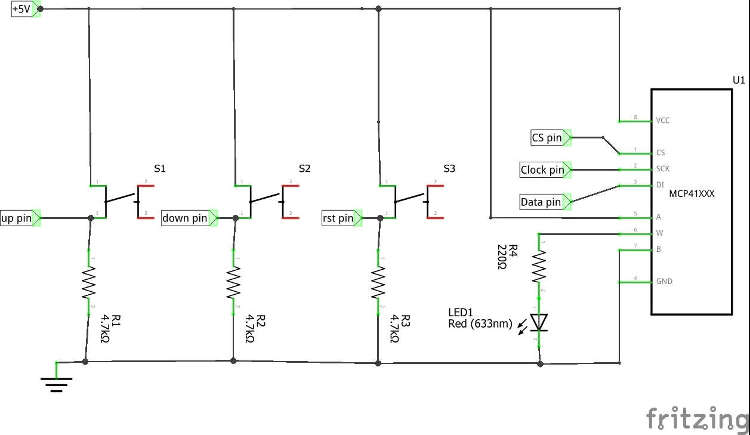
Schematic for SPI controlled potentiometer
Now paste the following code into Arduino studio then build and upload:
/*
* An example program demonstrating how SPI works using a few switches
* and a readily available potentiometer chip
*/

#include <SPI.h>

// chip selection pin on the potentiometer
#define POTENTIOMETER_CHIP_SELECT_PIN 25

// the up down and reset buttons connected on these pins
#define UP_BUTTON_PIN 22
#define DOWN_BUTTON_PIN 23
#define RESET_BUTTON_PIN 24

// in this example we have one set of SPI settings
SPISettings potSettings(256000, MSBFIRST, SPI_MODE0);

void setup()
{
	// Prepare the SPI library for use
	SPI.begin();

	// set the CS pin as an output.
	pinMode(POTENTIOMETER_CHIP_SELECT_PIN, OUTPUT);

	// set all button pins as inputs
	pinMode(UP_BUTTON_PIN, INPUT);
	pinMode(DOWN_BUTTON_PIN, INPUT);
	pinMode(RESET_BUTTON_PIN, INPUT);

	// set the SPI frequency and mode.
	SPI.beginTransaction(potSettings);

	// here we "select" the chip, transfer some data, and "de-select" the chip
	digitalWrite(POTENTIOMETER_CHIP_SELECT_PIN, LOW);
	SPI.transfer16(0x0000);
	digitalWrite(POTENTIOMETER_CHIP_SELECT_PIN, HIGH);

	SPI.endTransaction();
}
int count = 0;

void loop()
{
	// set the SPI frequency and mode.
	SPI.beginTransaction(potSettings);

	// "select" the chip
	digitalWrite(POTENTIOMETER_CHIP_SELECT_PIN, LOW);

	if (digitalRead(UP_BUTTON_PIN) == HIGH) {
		// button Up pressed, send a increment command
		SPI.transfer(0x04);
	}
	else if (digitalRead(DOWN_BUTTON_PIN) == HIGH) {
		// button Down pressed, send a decrement command
		SPI.transfer(0x08);
	}
	else if (digitalRead(RESET_BUTTON_PIN) == HIGH) {
		// reset pressed, send a 16 bit set with value command.
		SPI.transfer16(0x0080);
	}
	// "de-select" the chip
	digitalWrite(POTENTIOMETER_CHIP_SELECT_PIN, HIGH);

	SPI.endTransaction();

	// the delay acts like a very basic debounce for the switches
	delay(50);
}
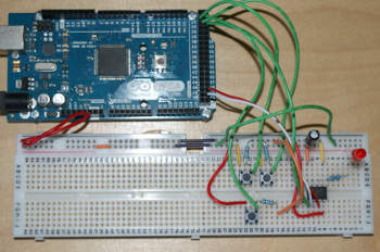
SPI potentiometer circuit assembled
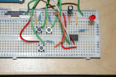
SPI potentiometer circuit assembled - close up
Other pages within this category
- SPI Serial Peripheral interface for Arduino tutorial
- Arduino to PC communication using USB serial and Java
- Message based communication using sockets.
- Using sockets for a character based stream
- Data communications by example for developers
You'll also find me on:

Also find me here