In this tutorial and accompanying youtube video (left), I discuss how Arduino inputs and outputs work. Arduino 8 bit
boards are mainly based on Atmel AVR chips, in fact the Mega is named after the chip number AVR-Mega-2560.
Outputs on the AVR chips are much more versatile than they first look, and the video covers this in detail.
If you are using an Arduino pro or other 3V3 based Arduino, replace the 5V mentioned here with 3V3.
If you've watched the video and want the slides, get the slides that go with the video here..
Firstly, let's get the absolute basics out of the way to make sure everyone is on the same level:
- To use an Arduino pin as an input or output, we must first configure it in the program set up using
pinMode(pinNumber, [INPUT|INPUT_PULLUP|OUTPUT]) - To read the current value we use
digitalRead(pinNumber). It returns LOW when the pin is near 0V, otherwise HIGH - To write a new value we use
digitalWrite(pinNumber, [LOW|HIGH]), low sets the pin close to GND, high close to 5V. - When the board starts all pins are in a high impedance state, we'll cover this in more detail in another article.
Using an Arduino pin as output
What is of interest about Arduino outputs, is that HIGH actually means act as a current sink (pin is at or near 5v) and LOW means act as a current source (pin is close to GND), see the video for more explanation of this. We can use this to our advantage, easily inverting logic without any additional components or chips, because whichever output state the pin is in, current will always flow through the circuit, it's not really ON and OFF.
Arduino pins are are spec'ed for 40mA of current each, but I suggest not willfully taking much more than around 20mA, one 3mm-5mm LED with a 220R resistor is somewhere between 10 and 15mA, depending on the LED's forward voltage and therefore completely safe.
It's so easy and cheap to buffer a pin for more power), that risking an expensive Arduino board for components that cost less than 1/100th of the price doesn't seem worth it.
Connecting an LED to an Arduino
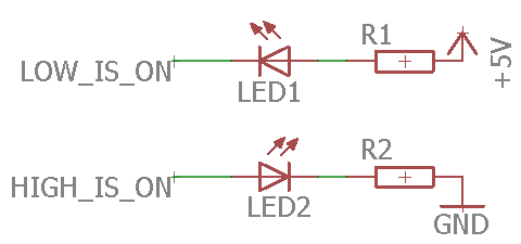
As an example of what we just discussed, let's say we want to connect an LED, but we want it to be on when the pin is LOW. In this case we just connect the LED in reverse between the pin and 5V instead of GND (see LOW_IS_ON in the diagram below). Conversely, if we want the LED to be on when the pin is HIGH, we connect in the usual direction as per HIGH_IS_ON in the diagram.
Using an Arduino pin as input
When an Arduino is configured as an input and unless you've used INPUT_PULLUP, it shows up as a very high impedance to the sensor or switch that it is connected to. From what I have read, it is in the order of 100M. To all intents and purposes, it will not affect readings unless your equipment is particularly sensitive.
When input pullup is used, the device enables an internal resistor between 5V and the pin, pulling the pin to 5V state.
An Arduino input should never be left floating - IE, not connected to anything such as an open switch. Doing so means the circuit will be unstable and pick up interference (switching the pin LOW and HIGH unexpectedly).
Connecting a switch to an Arduino
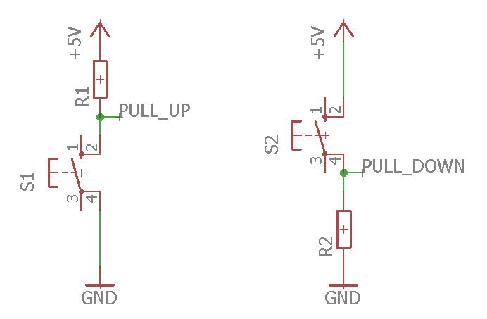
When we connect a switch to an Arduino board, we must ensure that the input pin is never floating, so we normally include a resistor of at least 4K7 if not 10K to pull the pin in one direction so it's always in a known state. There are two common ways that we can proceed:
- Normally LOW: The input pin will be LOW (connected to GND) when the switch is not pressed, going to 5V when pressed. We call this mode of operation PULL DOWN.
- Normally HIGH. The input pin will be HIGH (connected to 5V) when the switch is not pressed, going to GND when pressed. We call this mode of operation PULL UP.
Conclusion and more input and output pages
In this tutorial we covered the basics of using Arduino pins for input and output. We found that outputs are not ON or OFF, but rather LOW and HIGH and therefore far more versatile. We also found that inputs are generally very high impedance. At the end of the linked video I build an example circuit and show it operating.
These may be of interest
- Similar - Working with and de-bouncing switches for Arduino
- Similar - Troubleshooting and mock objects for testing
- Similar - Liquid Crystal fork example using IO Abstraction library - examples
- Similar - Arduino to PC communication using USB serial and Java
- Similar - SPI Serial Peripheral interface for Arduino tutorial

Want to let us know about something?
- If this is a library documentation page, raise a PR on the documentation site.
- Open a discussion on the Community channels
- Contact us for problems or improvements on the main site.
Supporting us
We maintain several popular embedded projects and work hard to make them even better. If you're looking for commercial services, please do consider us.
Alternatively, you can buy us a coffee to say thanks.
Sharing links
Learn about TcMenu
We build and maintain an embedded menu designer and framework that works on many platforms.