At the moment I am prototyping a high quality pre-amplifier based around the PGA2310 volume control and an op-amp buffer input with RF filtering. Each channel will be selectable by relay, along with gain adjustment for each channel in terms of increase in dB. Each channel will be assigned a name that can be changed easily in software and stored along with default volume and channel in the on-board EEPROM.
My aim is that this will run on a ATMega328 / Uno Arduino board. Needing only a few direct outputs, it will be able to interface with i2c 8574 IO expander devices. All devices used will be available in most locations. Further, it will be easy enough to build on vero board if you don’t fancy buying / making a custom PCB for it.
In addition to the above, there will be the ability to both monitor and control the device from a computer or phone using ethernet / RS232 over USB. This will be in the second phase, once I have all other functions working.
Unlike the building my honeybadger amplifier, where I followed a few well known designs and built a fantastic power amplifier, this time around I fancy building this pre-amplifier from the ground up (and even then you’re basing it on previous reference designs), mainly because there’s nothing I’ve seen that does exactly what I want.
It’s certainly not ready for anyone else to build yet, that’s why I’ve not yet shared any circuit diagrams / or software. If you subscribe to my twitter feed, I’ll provide an update as an when it’s further along.
I’ve built the amp on a mix of breadboard and vero board and it’s interesting enough to continue with. I’ve already managed to break one relay, on the test vero board, I forgot to break the base resistor track and essentially shorted the path from the arduino output to earth through the 26ohm resistance of the base. I think output 36 on my mega is broken as a result :(
Basic specs for this pre-amp when finished
What this preamp will have:
- Omron miniature G6K input relay switching (high isolation version needed)
- Input buffer opamp and PGA2310 device
- 20x4 display - probably high quality OLED
- Input and menu subsystem based on a library I’m building
- Interrupt based controls to avoid loads of nested busy loops
- Either RS232 or ethernet support for level monitoring and all menu functions
- Simple Android and Java client application that will monitor / control any number of devices.
Stretch goals
- Eventual phono stage for MM cartridges and high output MC
- Eventual possible digital source input over USB (may use an existing board design for this).
Block diagram of the preamp circuit components
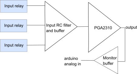
Hardware block diagram of the preamp
Block diagram of how the software will function
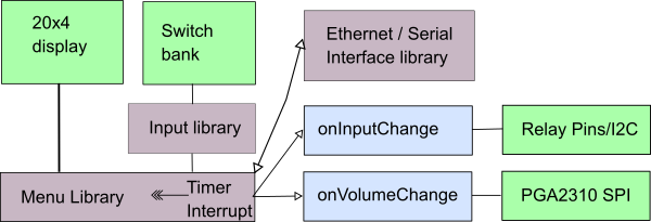
Above: High level block diagram of the software components
Key:
- light blue - code written for the preamplifier
- light green - hardware
- grey - libraries.
When we initialise the program in setup(), we will create a Menu and an Input object. These will take care of scanning the input and also rendering the menu onto the 20x4 display. This library is being built now, and will be general purpose enough to apply to a lot of designs. There will be an interface layer between the menu and the ethernet and serial layer available; which will allow IoT style control and monitoring via the menu library using ethernet / serial.
In the preamp’s own source file, most of the code will be in the form of callback functions when things happen, for example when the volume changes or when the input changes. These are shown in the diagram in blue.
Where it is now
It’s working in prototype form on breadboard. Things that need some attention:
- No RF filter and buffering at the moment, sounds a bit harsh from some sources, probably as a result.
- No IoT style control at the moment, no monitoring working.
- Input / Menu library not yet built - prototyped directly in the ino file.
Images of the build so far
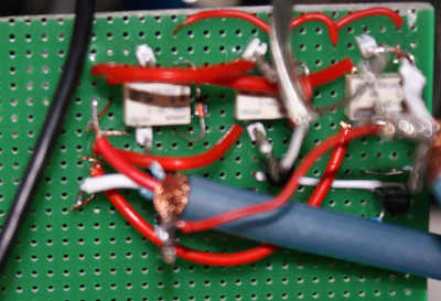
Relays mounted on vero-board
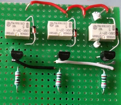
Relays vero-board without wiring
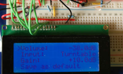
Example display board
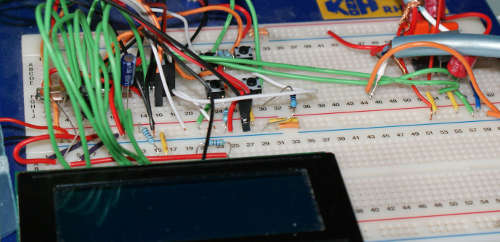
Preamp on breadboard assembly
You can see that as things stand, it is most certainly a prototype, running on a mix of vero and bread boards. I’m just doing a bit of wood working at the moment to get my garage in order. Once that is done I’ll be back onto this project.
Other pages within this category
- Designing a simple PGA2310 based preamplifier with network control
- Tidy up of my honey badger amplifier
- Building DIYAudio's honey badger amplifier
You'll also find me on:

Also find me here