When writing Arduino code that needs quite a few IO pins, you may need to expand the IO using a shift register or i2c expansion device such as the PCF8574. Up until now that meant significantly changing your code to use the new device. If you were using the io-abstraction library then you’d just set up a different type of IO.
This library allows you to treat shift registers and i2c exapnders almost as if they were pins. For library writers this provides an unparalleled way to support many different types of IO with very little downside and in one code base.
Getting the source
This library is hosted on our github account, it comes complete with many working examples showing both modes of operation. In addition to this, there is a fork of the LiquidCrystal library that works using this library, and therefore supports i2c and shift register operation.
- Main Git hub page [https://github.com/davetcc/IoAbstraction/].
- Documentation and more examples: io-abstraction library
- Fork of LiquidCrystal for shift registers and PCF8574
How IO abstraction library works
This library works by abstracting away the access to read and write data on pins, such that there is an implementation that works with Arduino pins direct, another for shift registers and yet another that uses an 8574 IO expander. Other chips could easily be added in the future and I’d happily accept pull requests or patches!
When using Arduino pins mode, there is very little overhead, it just calls directly out to Arduino underlying functions.
However, for serial operations, you really need to understand what the library is doing. As there is an overhead to
sending things over the wire, rather than sending each bit change one at a time, the library waits for a runLoop() call,
and then sends a write command if needed followed by a read.
For library writers
Many libraries could make use of this code, so I’ve put a very open and permissive license on it: Apache 2.0; which
allows commercial use. For the sake of example say we have a library called SuperLib that needs 6 IO pins, we could
first off have a constructor that took the 6 pins needed, assuming the pins were direct to Arduino ioUsingArduino():
SuperLib sf(PIN1, PIN2, PIN3, PIN4, PIN5, PIN6)
But then we could add an overloaded constructor, so that we could provide an alternative IO device such as a shift register or an 8574 IO expander:
SuperLib sf(PIN1, PIN2, PIN3, PIN4, PIN5, PIN6, ioUsing8574(0x20));
Trying out the IO abstraction library
In all cases include the library
#include <IoAbstraction.h>
For arduino pins
To create an instance for direct Arduino pins, simply:
IoAbstractionRef pins = ioUsingArduino();
To use an 8574 IO Expander
To create an instance for an 8574 IO expander provide the i2c address and include the Wire library:
#include <Wire.h>

IoAbstractionRef pins = ioFrom8754(0x20); // where 0x20 is the i2c address
To use shift registers
To create an instance that uses serial shift registers for read / write we would need a shift register for read and a shift register for write. We share the clock and data between the two chips, but we have two enable pins, that enables change on the registers output. If you are only using read, or write, you can use the two later functions. Because we need two shift registers and the directions are fixed, 0-23 are the read ‘pins’ and 24 onwards are the output ‘pins’. You can still call pin mode, but it won’t do anything on this variant. For more information about shift registers see [https://playground.arduino.cc/Code/ShiftRegSN74HC165N] and [https://www.arduino.cc/en/Tutorial/ShiftOut].
IoAbstractionRef shiftReg = inputOutputFromShiftRegister(readClockPin, readDataPin, readLatchPin, readClockEnaPin, writeClockPin, writeDataPin, writeLatchPin)
or
IoAbstractionRef shiftReg = inputOnlyFromShiftRegister(readClkPin, readClkEnaPin, dataPin, latchPin);
or
IoAbstractionRef shiftReg = outputOnlyFromShiftRegister(writeClkPin, dataPin, latchPin);
To configure input and output pins use the library instead of the usual pinMode call. Use standard Arduino constants for
INPUT and OUTPUT
ioDevicePinMode(shiftReg, 0, INPUT);
ioDevicePinMode(shiftReg, 6, OUTPUT);
In the main loop read and write values using the library. For the Arduino version, the pin number is used, for i2c 8574 it is the bit 0-7 of the port.
uint8_t switchValue = ioDeviceDigitalRead(shiftReg, 0);
ioDeviceDigitalWrite(shiftReg, 6, switchValue);

// this is absolutely needed on the serial versions, it makes it send the commands
ioDeviceSync(shiftReg);
Please take a look at the examples folder in the library, all the above cases are covered in detail.
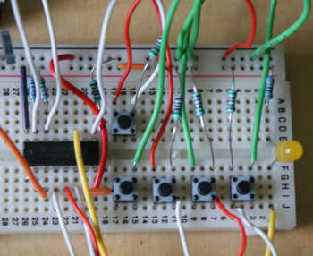
Built circuit examples
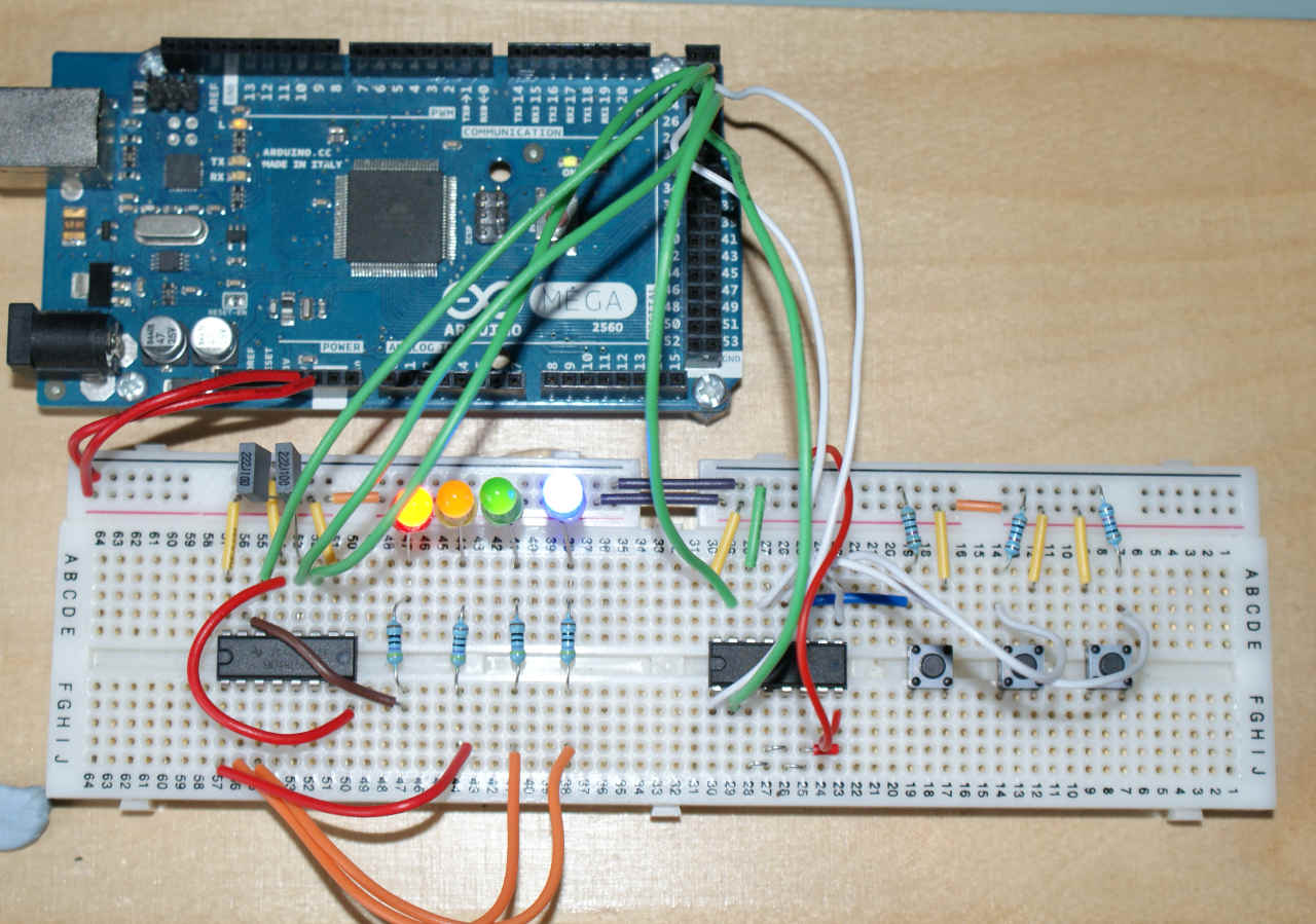
Using two shift registers - input and output - click for full-size
Using an 8574 IO Expander for input and output
Performance
Generally, for most cases where the amount of IO is limited, I believe this library is a good fit. If the library is constantly setting and testing bits thousands of times a second, then this library is probably not appropriate; but I’d argue that in that case neither is using an IO expander.
As far as I can tell, it uses no RAM beyond the object creation, the virtual method table usage is all in flash memory, so that should not be a problem for most devices. As far as I can tell, the shift register version is the heaviest on memory and probably worst on performance too. If you have a Mega chip then the i2c version will use hardware serial.
Reducing overhead
As the old saying goes, it’s better to work smarter than harder (although it’s often said at inappropriate times). Rather than polling for a transition, why not use the interrupt support available on the 8574 chip, and only read from it when needed. If you are bit blasting at a very high frequency or using PWM, you’re better off using Arduino pins directly.
Overhead involved in using serial IO / abstraction
There are few main sources of overhead in this library. For most cases, these should not pose a problem:
- it uses an abstract class with virtual method calls, AVR chips have no loop unravelling so cannot optimise out the jump.
- If you are using i2c, there is the obvious overhead of sending commands to the chip.
- There is an extra object, albeit small.
Other pages within this category
- Heltek Wifi kit 8 pin outs marked wrongly on some silk screens
- Arduino digital input and output tutorial
- IO abstraction: the same code for pins, shift registers and i2c IO
- Working with and de-bouncing switches for Arduino
You'll also find me on:

Also find me here